Using the voltage doubler
A Simple voltage-regulated supply for the VFO.
A simplified discussion of the principles of voltage-doubling circuits and voltage-regulator tubes for the beginner. Included is an example of practical application in a small power supply for a VFO.
As the novice proceeds in his thinking and planning about the "big rig" he will have after attaining his General ticket, one of the considerations will naturally be the type of variable-frequency oscillator, or exciter, which he will use to drive the final. There are many good circuits in the literature today which will fill the bill nicely. In addition, there are available several good pieces of surplus military equipment which, with minor modifications, serve the purpose of a stable VFO. However, any of these is only as good as its power supply, for stability of the oscillating frequency is usually very dependent on the regulation of the voltage applied to the plate of the oscillator tube.
The circuit to be described and illustrated in this article delivers just such a regulated voltage at a minimum of cost and effort, and its construction serves to acquaint the builder with the operation of voltage doublers as well as the voltage-regulator tube.
The author decided to make use of a Command-series transmitter as a VFO. For the 80-meter amateur band, either the T-19/ARC-5 covering from 3 Mc. to 4 Mc., or the BC-457 covering from 4 Mc. to 5.3 Mc., may be used with very little modfication. The major requirement for putting either of these units into operation is an adequate power supply. The high-voltage supply may be of the standard type, with an output of from 500 to 750 volt. However, the supply used for the oscillator plate and screen of the amplifier tube should deliver about 210 volts at 35 mA and have good regulation.
The junk-box parts which were available dictated, in part, the type of supply which was built. It was felt that an isolating transformer was necessary as a matter of safety. The only transformers available were of 1:1 ratio with a 40-ma. rating. In other words, with 115 volts on the primary, the secondary delivered about 115 volts under load. This was only about half of the required 210 volts, so it was decided that a voltage-doubler circuit was the answer. However, as usual, one does not get something for nothing. In doubling the voltage, the current which may be drawn from the transformer is cut in half. Thus, two of the small 1:1 transformers were connected in parallel. These transformers are inexpensive and are available from supply houses as TV booster transformers.
Circuits
There are several different voltage-doubler circuits in common use and it was felt that a brief look at a few of them might be beneficial before selecting the one for the regulated supply. The circuit in Fig. lA illustrates one type of voltage doubler. It has the advantage that, if the unit is operated directly from the a.c. line, one side of the output is common with one side of the input and may be connected so that this common side is grounded. A disadvantage is that the output is equivalent to that from a half-wave rectifier and should have further filtering circuits to smooth out the a.c. ripple.
Before beginning to analyze these circuits, it might be wise to clear up any possible confusion in the beginner's mind over the symbol used to represent a selenium rectifier in a schematic drawing. The conventional symbol for a selenium rectifier has an arrowhead pointing in the direction of least resistance. The arrow head corresponds to the plate in a tube rectifier, and the bar corresponds to the cathode. If this is kept in mind, the operation of these voltage-doubler circuits is very simple.
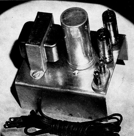
A simple voltage-regulated supply for the beginner. This top view shows one of the two isolating transformers, the dual electrolytic capacitor, and the two 0B2 regulator tubes.
Looking again at Fig. 1A, it will be seen that, when the alternating input voltage swings negative (upper terminal negative in respect to the lower terminal), selenium rectifier CR1 passes electrons against the arrowhead and charges capacitor C1 to nearly peak line voltage, or about 150 volts. Resistor R limits the surge current when C1 first charges. If the capacitor is electrolytic, it must be connected with the polarity shown in the diagram. The capacitor then is charged with its left plate negative and its right plate positive. During the next half cycle, when the input polarity is reversed, the 150 volts across C1 is actually connected in series with the line-voltage source and the total voltage across CR1 is twice peak line voltage, or about 300 volts. However, CR1 will not pass electrons, for they cannot flow in the direction of the arrow. But, at this point, CR2 does conduct, and proceeds to charge capacitor C2 to nearly 300 volts. This process repeats once each cycle of the line voltage and is therefore similar to a half-wave rectifier output. The working voltage of C2 obviously must be twice that of C1, or on the order of 400 volts as a minimum.
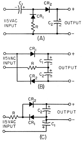
Fig. 1. Typical voltage-doubler circuits.
Another voltage-doubler circuit is illustrated in Fig. 1B. From some standpoints, this is one of the best circuits for achieving a multiplication of voltage. It is equivalent to a full-wave rectifier, and it has no capacitors in series with the output. This means that a minimum of filter is required to eliminate a.c. ripple.

Bottom view of the simple voltage-regulated power supply. The second isolating transformer is mounted underneath the chassis, along with the selenium rectifiers.
In this circuit, when the line voltage swings positive, CR1 conducts electrons to the left, charging C1 to about 150 volts with the polarity shown. During the negative half cycle, CR2 conducts electrons to the right, and charges C2 to 150 volts as shown. R again limits surge-current flow through the rectifiers. Now it may be seen that C1 and C2 each have a charge equal to peak line voltage and, since they appear connected in series aiding at the output terminals, this voltage under no-load conditions is almost 300 volts. Of course, as current is drawn from any of these voltage doublers, the capacitors maintain an average charge somewhat less than peak, and the output voltage drops off fairly rapidly. If moderately large capacitors are used, currents on the order of 100 ma. are easily obtained without excessive loss of voltage.
As a last example of a voltage-doubler circuit, refer to Fig. 10. Here C1 is charged through CR1 during the negative half of the input cycle, and then its charge is effectively in series with the line voltage during the positive half of the cycle, at which point C2 is charged to twice the peak line voltage through CR2. This is again similar to a half-wave rectifier and has the disadvantage of a series capacitor in the output. However, it does have one convenient advantage. The two capacitors have their negative terminals connected to a common point. This means that both size and cost may be conserved by using a dual capacitor with a common negative terminal. If a filter network consisting of a choke, or resistor, and another capacitor is desired, a triple-unit capacitor may be used, since all three will have a common negative terminal.
Since space was at a premium and the current requirement of the BC-457 was only moderate, the circuit selected for this regulated power supply was that of Fig. 1C. Fig. 2 shows the actual circuit used. As mentioned earlier, two transformers were used in parallel to supply the required current, since these were already on hand. For the same reason, four 35-ma. rectifiers were used where only two of 50-65 ma. capacity would have sufficed. If one is planning to build this unit using newly-purchased parts, it is recommended that adequately-rated single components be used for the transformer and selenium rectifiers in the interests of economy.
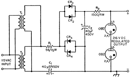
Fig. 2. Circuit of the simple voltage-regulated power supply. Each pair of 130 volt 35 mA selenium rectifiers may be replaced with a single 130 volt 65 mA, unit. The capacitors may be separate units, or combined in a dual unit. T1,T2 - Isolation (TV booster) transformer, 115 volt primary, 115 volt secondary, 35 mA or greater (Triad R-30X, Merit P-3045, Chicago PV-50A, Thordarson 22R12, etc.). These two transformers may be replaced with a single unit of higher-current rating, such as the Merit P-3096 or UTC R-72.
VR tubes
Since voltage-regulator tubes have the property of maintaining a relatively constant voltage across them, regardless of the current through them within certain limits, they act as very good a.c: ripple filters and, consequently, no further filtering was necessary in this supply. Selecting the proper value of R2 is very important in obtaining the desired regulation, so a brief explanation of the operation of a voltage regulator may be in order.
A voltage-regulator tube consists, generally, of a cylindrical plate surrounding a small-diameter rod cathode, and is sealed in an inert gas atmosphere inside of a glass envelope. If a certain minimum "firing" voltage is applied across the tube (positive to the plate and negative to the cathode), the gas ionizes and a current flows from the cathode to the plate. That is, electrons are freed from the gas atoms and are attracted toward the positive plate. At the same time more electrons leave the cathode and recombine with the electron-shy atoms, or positive ions. The result is a steady flow of electrons into the cathode terminal and out of the plate terminal.
The 0B2 used in this circuit has a minimum firing potential of 133 volts or, for two in series, 266 volts. Once the tubes conduct, the voltage across each tube drops to 108 volts and will remain within ±1 volt of this value over a range of 5 to 30 mA through the tube.
If the total voltage across the two OB2s tend to rise with changing load, the tubes immediately draw more current in proportion to the increase in voltage. This increase in current must flow through R2, and consequently causes an increase in voltage drop across R2, with the result that the voltage across the voltage-regulator tubes remains very nearly constant.
In using this regulated power supply, with the BC-457 surplus transmitter serving as a variable-frequency oscillator, it was decided to key the 1626 oscillator tube. When the key is open in the arrangement used, there is a minimum of about 10 ma. being drawn from the supply by the screens of the r.f. amplifier tubes and, when the key is closed, the maximum load is about 35 ma. The difference between the maximum and minimum loads, or 25 ma., must be absorbed by the voltage-regulator tubes when the key is open. The tubes will extinguish if less than 5 ma. load flows through them, and it is wise to allow another 5 ma. as a safety factor. Therefore, when the transmitter exciter is drawing its maximum load from the power supply, R2 must be of such a value that approximately 10 ma. flows through the VR tubes at the same time. Then, when the key is opened, the load change of 25 ma. is added to that already flowing through the VR tubes, making a total of about 35 ma. This is 5 ma. more than the manufacturer's rating for this tube, but amateur equipment is generally used much more intermittently than commercial equipment, and this small overload will not shorten the tube's life appreciably.
R2 has been selected to give proper operation under these particular load conditions. If a greater load is imposed on the power supply, the VR tubes will extinguish and the output will no longer be regulated. Regulation may be restored by decreasing the value of R2. R1 again limits the surge current through the selenium rectifiers and its value is not critical.
William L. Blair, W3ZKE.