6AN8-6BQ6 modulator
Audio power for 25-50 watt transmitters.
Here is a modulator designed especially for transmitters in the 25-50 watt class such as the Heathkit AT-1, Viking Adventurer, Eldico TR-75TV, etc. Good performance, simple construction and low cost are some of the features that make this a worth-while project for the budding phone man.
Although the amateur bands sometimes seem to be filled only with high-powered phone signals there are still a lot of medium-and low-powered stations in there pitching. The amount of r.f. power being used is an important factor but unless the carrier is fully modulated with an undistorted audio component your chances are slim for making those solid contacts.
Of all the different types of modulation, plate modulation is the most effective for low power. You can try to save money by using other methods of modulation but you're just spinning your wheels unless you can boast of a high-power r.f. amplifier. If grid or screen modulation is used with a 50 watt transmitter only a few watts output can be expected. So, to get the most out of your transmitter, moneywise and powerwise, plate modulation must be used.
If you are using a rig in the 50-watt input (or lower) class, whether home-built or a new commercial job, this is the plate modulator for you. The modulator has an output of 25 watts with little distortion and contains its own power supply. Two connections to your c.w. rig will give you a phone transmitter you will be proud to use.
Circuit
The circuit, shown in Fig. 1, is based on providing ample gain from an inexpensive communications type crystal or ceramic microphone. With an input of 20 millivolts at the microphone jack the modulator is capable of 25 watts output. A 6AN8 pentode-triode is used as a speech amplifier. The microphone output is amplified in the pentode section and fed into the triode part of the tube by resistance coupling. Output from the triode is transformer-coupled to the grids of the modulator tubes, which may be any of the several varieties of 6BQ6s (GTA, GTB/ 6CU6, etc.). Although the 6BQ6 does not ordinarily carry an audio rating, having been designed for TV sweep-circuit work, it has an advantage over tubes such as the 6L6, for example, in that it will develop a given power output, within its capabilities, at relatively low plate and screen voltages. This saves considerably on power supply cost. Also, the tube itself is inexpensive.
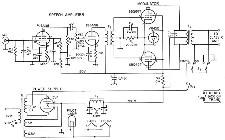
Fig. 1. The speech amplifier-modulator circuit. Capacitances are in µf. Capacitors with polarities marked arc electrolytic. Others are ceramic except the 0.01 µF unit, which is paper. All resistors ½ watt unless specified otherwise.
| L1 8 H, 150 mA (Thordarson 20054). |
| S1 S.p.s.t. toggle switch. |
| S2 D.p.d.t. toggle switch. |
| S3 2 pole 2 position rotary switch (Centralab PA-2003). |
| T1 Power transformer, 650 v. c.t., 150 mA (Thordarson 22R06). |
| T2 Interstage transformer 1:3 primary-to-secondary ratio (Thordarson 20A22). |
| T3 Modulation transformer, 4000-4000 ohms (UTCS-19). |
The power supply, using capacitor input, has an output of about 300 volts under load. The voltage for the speech amplifier and modulator screen grids is obtained from the same power supply through a dropping resistor. A VR150 regulates this voltage on the screens at a constant 150 volts, regulated screen voltage being highly desirable in a Class AB amplifier. The VR tube also contributes to the power supply filtering for the speech amplifier. Note that it is connected between the screens and cathodes of the 6BQ6s, not from screens to ground. This makes the screen-to-cathode voltage an actual 150 volts, not 150 reduced by the grid bias developed in the 270 ohm cathode resistor. Maintaining the full screen voltage on the 6BQ6s is important, because the power output depends critically on screen voltage.
Bias for the 6BQ6 modulators is obtained from the cathode resistor R1. About 45 volts of bias is obtained with the 270 ohm resistor and this voltage is subtracted from the plate voltage. If a battery of about 30 volts is used for bias, eliminating R1 and C3 and grounding the 6BQ6 cathodes, the output is about 30 watts as a result of the effective increase in plate voltage.
The capacitor C2 on the primary of the modulation transformer is used to attenuate the high frequencies, and thus cut the frequency response of the amplifier to the most useful range for voice work. It is helped out in this by capacitor C1 at the microphone input, which in addition provides an r.f. by-pass to ground.
For operating convenience, a send-receive switch, S2, and a phone-c.w. switch, S3, are built into the modulator. By connecting leads from S2B to the key jack on the transmitter, the entire transmitter can be controlled at the modulator. The phone-c.w. switch shorts the modulation transformer and turns off the modulator high voltage when operating c.w.
Layout and Construction
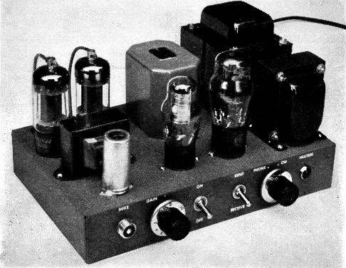
The modulator is constructed on a 7 × 11 × 2 inch chassis. The speech amplifier-modulator is at the left of the chassis and is separated as much as possible from the power supply. The output plug and line cord are located on the rear of the chassis.
One of the most important things to remember when laying out a modulator is to place the components for the least amount of a.c. hum pick-up. Particular attention should be given to the power transformer, filter choke and leads carrying a.c. All of these should be kept as far away as possible from high-gain input circuits and unshielded interstage transformers. As shown in the photographs, the microphone input, speech amplifier tube and interstage transformer are all placed at one end of the chassis with the power supply components at the other. It is also a good idea to separate the input stage from the modulation transformer to prevent feed-back.
The modulation transformer is a UTC S-19 and all of the terminals are located on the bottom of the case. Three holes (made with a tube socket punch) side by side will give enough room to connect leads to the terminals.
The hardest job is mounting the power transformer. Most of the "economy" transformers are made to mount in a large square hole in the chassis. Although the average ham usually has an assortment of drills and tube socket punches, it is quite a job to start forming square holes for transformers. Some transformers come supplied with brackets and others are made to mount in an upright position which presents no mounting problems. But if you're stuck with an old receiver power transformer or don't want to pay the extra cost of the easy-mounting kind, it is a simple matter to connect the transformer to the chassis. If you're lucky enough to find them at a hardware store, four 8-32 machine screws about four inches long will hold the transformer on top of the chassis with the leads running through a grommetted hole. If you're one of the fortunate few who have threading tools, you can thread some Krinch rods at both ends and mount the transformer above the chassis. In either case, some spacers (made from copper tubing, etc.) placed between the chassis and the transformer will hold it in place. Another method (as a last resort) is actually forming the square hole. Several round holes are made with a socket punch to form a rough hole, and then a file is used to square it up to size.
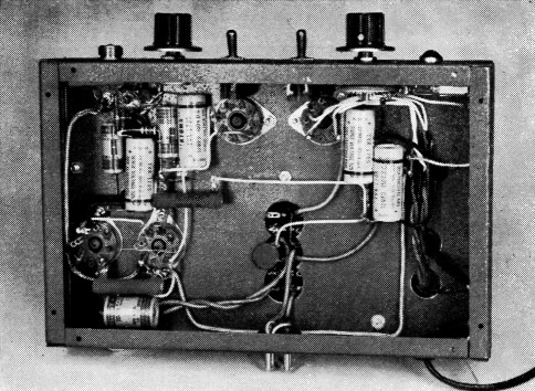
Bottom view showing placement of components. The two large capacitors at the right are the filter capacitors in the power supply. The bias resistor and bypass capacitor (Rt, Ca) are in the bottom left of the chassis. Notice the three holes (made with a tube socket punch) which allow leads to be connected to the modulation transformer. Shielded wire is used for heater, microphone input and gain-control leads.
The other components such as tube sockets, operating controls and plugs are mounted in the usual manner. Before tightening the screws on these components, ground lugs and terminal strips should be attached. A ground lug at each tube socket is a must, and a few more located near the power supply will help. Terminal strips make excellent tie points for filter condensers and other small components such as resistors and by-pass condensers.
Operating notes
The impedance ratio required in the modulation transformer depends on the load represented by the Class C amplifier, and the transformer taps must be chosen to reflect a 4000-ohm load, plate-to-plate, to the 6BQ6s. The Class C load is found simply by dividing the Class C plate voltage by the plate current (including the screen current) and multiplying the result by 1000. For instance, if the transmitter is running 400 volts at 100 mA (to the final amplifier) the resistance is 4000 ohms. In this case the impedance ratio (and turns ratio) would be 1 to 1.
If a multimatch transformer is used, the taps that will most closely match the required impedances should be used. A chart will be included with the transformer showing how to make the desired connections.
To connect this modulator to a Heathkit AT-1 transmitter, the jumper between Pins 3 and 4 of the modulator plug on the transmitter should be removed. Leads from the modulation transformer are then connected to Pins 3 and 4 on the modulator plug.
For the Johnson Viking Adventurer, the jumper is removed from Pins 4 and 5 of the modulator socket. Leads are connected from the modulation transformer to Pins 4 and 5 on an octal plug which is inserted in the modulation socket on the transmitter.
It is not generally considered good practice to modulate an amplifier that is frequency-doubling, so if this modulator is to be used with a doubling-type transmitter such as the Heathkit AT-1, it is a good idea to make the modifications described in the article, "More Power with the AT-1," October, 1955, QST, page 36.
For checking purposes, a 0-200 mA meter can be connected in the plate circuit of the modulator tubes. The meter is inserted in series with the lead that runs to the center tap on the primary of the modulation transformer. The average values of current will vary slightly but the static current (current with no signal) should be about 50 mA. At full output from an audio tone signal the current will swing to about 165 ma., but the same peak output from voice signals will cause the meter to kick only to about 60 to 70 mA. The plate current of the Cass C amplifier in the transmitter should stay constant with modulation.
When using the modulator with your transmitter, care should be taken not to operate at more than 100 per cent modulation. Several methods of checking modulation percentage are described in The Radio Amateur's Handbook.
The modulator should never be operated without the Class C load, or an equivalent resistance, on the output transformer; the transformer may break down because high voltages are developed under such conditions. A 25-watt resistor of the same resistance as the Class C load can be used as a dummy load for checking power output and wave-form as described in the Handbook.
E. Laird Campbell, W1CUT.