The "EZ-Couple"
Coupling odd antenna lengths to the rig.
Many times an odd length of wire is the only antenna an amateur can use at his location. The simplest antenna coupler that will insure proper coupling between the wire and a low-impedance output transmitter is the "L" coupler described in this article. If, for one reason or another, you are one of the unfortunates who can't put up a textbook antenna, here is the next best solution.
The following is an excerpt from a recent letter to Headquarters: "I have a problem concerning an antenna installation for my shack. I am located on the second floor of an apartment in a development which does not allow any outside antenna. I have an antenna in mind which I can install on my window sill and use it during the nighttime. Can you help me?" This is a type of question that turns up quite frequently in our mail bag, indicating that many amateurs are confronted with the same problem.
Probably in about 90 per cent of the cases an amateur can string up a wire somewhere. It will work better if it is high and in the clear, but this is not always possible. With a "random" wire of this type (it usually doesn't work out to be a textbook length of ¼ or ½ wavelength) the remaining problem is to load the transmitter with it. To handle all cases, an antenna coupler is required.
There is nothing new about the system but it bears repeating for the benefit of the new crops of amateurs that have come along in recent years. Briefly, the system consists of using an L-section coupler, which can be used to couple power from the transmitter to an antenna of any length. By "any length" we mean the antenna should be as long as possible, but a wire as short as 20 feet will work on 80 meters.
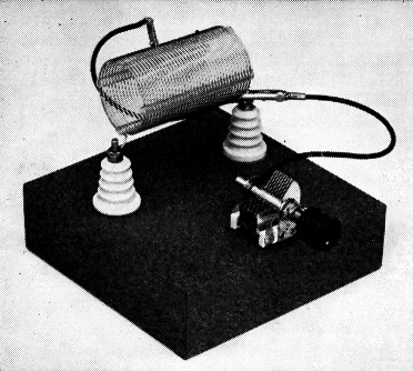
The coil is mounted on the stand-offs by wrapping the ends of coil around the screws and tightening the nuts. The wire size is large enough to furnish sufficient rigidity for this type mounting.
In testing the coupler shown in the photographs and in Fig. 1, a 20-foot length of wire proved to be sufficient to produce three contacts on 80, and two on 40. This was with the antenna entirely indoors in the second-floor shack of a frame house. The power input was approximately 50 watts.
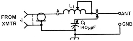
Fig. 1. Circuit diagram of the antenna coupler. L1 - 30 turns No. 16, 10 turns per inch, 2 inch diam.
Coupler details
As can be seen from the circuit diagram, the coupler is very simple. The inductance L1 is obtained by using part of a length of Air Dux 1610S coil stock.(1) The proper amount of inductance for a given antenna and frequency is obtained by shorting out a portion of L1. A clip lead is used to connect the stator plates of C2 to point A or B, depending on the antenna length and the frequency of operation.
Any type of variable capacitor that has a maximum capacitance of approximately 140 pF can be used. For inputs up to 75 watts, 0.025 inch plate spacing is sufficient.
Construction
The coupler described here was mounted on a metal chassis. However, if one desires, the unit can be built on a piece of board, saving the cost of a chassis. If the unit is bread-boarded, a common ground bus can be made from a length of wire. The bus connects J1, C1, and the ground terminal together. A coax fitting was used for the input terminal because these days most transmitters are built to work into a coaxial line.
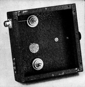
Bottom view of the coupler showing the input and output terminals. If the smaller type coax is used, a shielded phono jack can be substituted for the more expensive coax socket.
Using the Coupler
To make the tune-up of the coupler easier, a table is given that shows the tap points for the various bands with antennas up to 100 feet in length. There might be a slight variation in the tap position with the lengths given because of different ground conditions, surrounding objects, height, etc. The tests described here were made with an antenna approximately 25 feet above ground.
If you are able to get any of the antenna outside the building, by all means do so - you'll have a better chance of making contacts. Bring the shack end of the antenna to the output terminal of the coupler. If an r.f. ammeter is available, connect it in series with the end of the antenna and the output terminal. Otherwise, a No. 44 or 46 dial lamp can be connected in series with the antenna and used as an output indicator. If the antenna end approaches a current loop, the light bulb will light up. If the end is near a voltage loop, a neon bulb can be used as an indicator. If you find that the dial lamp burns too brightly, connect another lamp in parallel with the first, or shunt the lamp with a 6-inch length of small wire.| Ant. Length | 80 (Turns) | 40 (Turns) | 20 (Turns) | 15 (Turns) | 10 (Turns) |
|---|---|---|---|---|---|
| 100' | 18½ | 7½ | 6½ | 4½ | 2½ |
| 90' | 18½ | 9½ | 4½ | 4½ | 2½ |
| 80' | 18½ | 11½ | 3½A | 4½ | 2½ |
| 70' | 18½ | 15½ | 5½A | 4½ | 1½ |
| 60' | 18½ | 21½ | 8½A | 4½ | 1½ |
| 50' | 18½ | 15½ | 6½A | 4½ | 1½ |
| 40' | 18½ | 11½ | 5½A | 4½ | 1½ |
| 30' | 28½ | 2½A | 6½ | 4½ | 1½ |
| 20' | 28½ | 7½ | 6½ | 4½ | 1½ |
(A) Indicates stator of C1 connected to input side of L1.
All unused turns are shorted out.
The tune-up procedure consists of resonating the final amplifier of the rig, and then adjusting C1 and the tap on L1 for maximum output as shown by the indicator used. The amplifier tuning should be rechecked for resonance after each adjustment is made on C1L1. And the input must be held to the same value if the output indications are to be compared.
If a good connection to an earth ground is available, it can be connected to the ground terminal. This may be of help in keeping metal objects in the shack from getting "hot" with r.f.
The important point to remember is to work for maximum output (at constant input) as shown by your output indicator. Under certain conditions, a good deal of power can be lost as heat in the coil if improper settings of C1L1 are used.
As mentioned earlier, the system may not be as good a performer as more elaborate installations but it will produce contacts. One last point - it may be that because of circumstances beyond your control an objection would be raised to any wires or aerials around or near your shack. W6ZMZ wrote an excellent article on the use of "Invisible antennas" in February, 1949, QST. You might swipe a copy from some amateur friend, or get one from Headquarters, as it is required reading for hams with an uncooperative concierge.
Notes
Lewis G. McCoy, W1ICP.