How to tune to A.M. phone
Using the crystal filter to best advantage.
Although the receiving method described here has been around a long time, only a few of the more cagey phone operators have been taking advantage of it. It doesn't cost anything to give it a try.
From contacts with amateur groups in various parts of the country it is evident that comparatively few operators are aware of the potentialities for better phone reception inherent in a receiver of ordinary design. The "conventional" method of reception, in which a.v.c. has the dominating role, requires little or no skill on the part of the receiving operator; it is hardly more than "BCL-type" tuning. But the amateur who is willing to exert a little effort will be surprised at how much can be done to reduce interference in a.m. phone reception, by using more advanced tuning techniques that utilize the possibilities built into any good-grade communications receiver.
The kind of receiver we're talking about is one that has reasonably good frequency stability and a garden-variety crystal filter. Receivers that meet these specifications have been on the market for the past two decades.
Carriers and a.v.c.
Although there is always a lot of talk about sidebands, two real villains in the QRM act usually get by unsuspected. Acting hand in glove to circumvent the selectivity built into the receiver, these two are the carrier of the a.m. signal and the a.v.c. system of the receiver. It happens, unfortunately, that they are sacred to some of the a.m. population, and since any real improvement in selective reception (with the class of receiver we have in mind) will hinge on getting rid of both of them, we can probably say farewell to a portion of the audience right now.
However, those that are left probably will be interested to know why the carrier and a.v.c. are being put on the spot. It's pretty largely tied up with the process of detecting an a.m. signal. The familiar type of a.m. detector - a diode, usually - is a "linear" rectifier which gives a varying d.c. output that reproduces the modulation en velope of the incoming signal. This is fine when only the desired signal gets through the selective circuits of the receiver to actuate the detector. Conditions are not always so ideal, though, and very often an interfering signal will be close enough to the desired one to get through, too. Now detectors of this type have the peculiarity that when more than one carrier is present the strongest one tends to suppress the modulation on the weaker ones. If the desired signal happens to be one of the weaker ones, the interfering signal "takes over." In this it is abetted by the a.v.c. action of the receiver, which will respond to the strongest carrier present at the a.v.c. rectifier and reduce the r.f. gain accordingly, thus pushing the desired signal farther down into the background. The heterodyne squeal that accompanies this doesn't improve the situation, either.
There is an obvious remedy: Don't let any undesired carrier ever get stronger at the detector than the desired one. This simply requires high enough selectivity. But as the selectivity is increased - and it has to be quite high when the carriers are separated by only a couple of hundred cycles - the sidebands of the desired signal become more and more attenuated. Sufficient selectivity to take care of practical cases of interference not only greatly reduces the audio output of the detector but concentrates what is left in the low audio region, so speech becomes "drummy" and loses intelligibility. That is just what happens when the crystal filter is advanced notch by notch to increase selectivity to take care of bad QRM. This method of coping with the situation, although universally practiced, leaves a lot to be desired.
Another approach is that of "exalting" the desired carrier; that is, using a high-selectivity channel to amplify the carrier only - using many times the amplification given the entire signal, which is handled by a second channel of sufficient width to pass the sidebands. The much-amplified carrier is then combined with the sidebands in the final detector. This works well but takes a rather elaborate receiving set-up, and is out of the question with our standard communications receiver. (Actually, a form of exalted-carrier reception is possible with an ordinary crystal filter if its sharpest position is really sharp. However, it imposes such severe stability requirements that it is not very practical with most receivers, and in addition the audio output from the detector is very much below normal. Those who are interested can find the method described in QST several years ago.(1)
However, there is still another method. The essentials of it are in everyday use, but not often for a.m. reception. The basic idea is simple: If there is no easy way to exalt the incoming desired carrier without introducing some other undesirable effects; then let's get rid of the carrier entirely. It serves only two purposes in reception: to provide a steady frequency against which the sideband frequencies can beat and thus produce the audio output, and to actuate the a.v.c. system. The former is a necessity and the latter is merely a convenience. But any steady r.f. voltage of the same frequency as the carrier will serve equally well in place of the actual carrier for detection purposes.
Certain conditions must be met. The substitute carrier must be at least as strong, at the detector, as the original carrier; otherwise there will be distortion because the detected signal will be overmodulated. However, this is taken care of automatically since the whole purpose of substituting a locally-generated carrier is to get one much stronger than any carrier that might be tuned in. The other condition is that, if both sidebands are passed through the receiver's selective system to the detector, the substitute carrier must have the same phase as the original carrier. This would be so difficult to accomplish (and maintain) that the whole scheme would be impractical, if accomplishing it were actually necessary. Fortunately, it isn't. The phase requirement, and much of the stability requirement along with it, disappears if one of the incoming signal's sidebands is eliminated along with the carrier.
In other words, the a.m. signal is turned into an s.s.b. signal before detection. Yes, it requires much the same sort of tuning that a real s.s.b. signal does - strong medicine for some to swallow, no doubt, but it provides a real answer to the selectivity problem. Actually, the tuning is easier than with pure s.s.b., as will be seen.
In eliminating the carrier, a.v.c. operation is also automatically eliminated in practically all receivers of the type under consideration. It could be restored (at least in some cases) if it seemed worth while, by a revision of the i.f. system. It isn't essential.
A.M. into S.S.B.
The key to this kind of reception is the crystal filter. It has a type of selectivity that is very well suited both to carrier rejection and selection of one sideband. A fairly broad setting of the filter selectivity control is capable of handling most interference. Fig. 1 is typical of the response curve of a crystal filter and i.f. amplifier at such a selectivity setting. The frequency scale is plotted a little differently than is usual, in that the frequency is in terms of departure from the frequency at which the phasing notch is set. The incoming carrier is eliminated by dropping it into the phasing notch; by this means it can be attenuated some 40 db. or more below the amplitude it would normally have at the second detector.
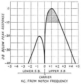
Fig. 1 This is typical of the relative response of a crystal filter, with its associated i.f. amplifier, at a moderately broad selectivity setting, with the phasing notch set 1 kc. off the filter peak on the low-frequency side. The useful response band of the filter is about as shown by the shaded region. If an a.m. signal is tuned so its carrier is exactly in the notch, the lower sideband is attenuated a minimum of about 20 db. as compared with the upper sideband, and the signal becomes essentially a single-sideband one.
The notch is always offset from the peak frequency of the crystal (should the phasing control be set to neutralize the holder capacitance exactly, the notch will disappear and the resonance curve will be practically symmetrical about the peak frequency) and this is responsible for the fact that the response on one side of the notch is many decibels below the response on the other side. In the figure, the attenuated side is the low-frequency side and the pass-band is on the high-frequency side of the notch. This state of affairs can be reversed by adjustment of the phasing control. It is also possible to change the frequency separation between the notch and the peak, as indicated in Fig. 2, again by adjustment of the phasing control. None of this is news to those who have made a point of observing what happens when the filter controls are manipulated. Many have not, however, and it helps to know how the filter operates when using it for the type of reception under consideration.
Suppose the selectivity curve is as shown in Fig. 1. Tuning in a signal is the same thing as moving it across the selectivity curve. At one setting of the tuning control, the carrier will drop down into the notch. This lets the upper (at i.f.) sideband on the signal pass through, but greatly attenuates the lower sideband. Essentially, we now have a single-sideband suppressed-carrier signal at the second detector, although it is a normal a.m. signal at the crystal-filter input. Thus the first step is accomplished.
The only thing remaining is to supply a substitute for the original carrier. Most readers will be way ahead of us by this time - the b.f.o., of course. Its frequency is simply adjusted to be the the same as that of the rejected carrier - to the identical frequency at which the phasing notch is set, in other words. The b.f.o. supplies a constant r.f. voltage to the second detector, a voltage that can always be made much larger than that of any incoming carrier. The simplest way to maintain this voltage relationship is to keep the r.f. gain down, by means of the manual gain control, with the a.v.c. off. Any loss in audio volume can be regained by opening up the audio gain control. In fact, the best way to operate is with the audio gain full on and the r.f. gain cut back to give a comfortable level of audio output. Best, that is, if you have a receiver that doesn't get noisy when operated this way. More later on this point.
Voice frequency response
A commonly-voiced objection to the crystal filter for phone reception is that it is "hoomy" or "drummy" or "doesn't sound natural." This is because the selectivity is such that, as used in conventional reception, the higher-frequency components in the sidebands are badly cut. "Normal" reception places the incoming carrier on the peak of the selectivity curve, so if the curve has a useful width of, say, 1500 cycles, both sidebands suffer undesirably high attenuation above 750 cycles.
With the method of reception just described, the same selectivity can be used to make the signal sound normal, tinny, or almost anything you like. In the first place, the a.f. output from the detector has the same bandwidth as the selectivity curve, not half of it as in double-sideband reception. Thus the identical r.f. selectivity gives twice the audio bandwidth. In the second place, the available bandwidth can be placed in practically any desired section of the a.f. spectrum. Suppose that the shaded area in Fig. 1 represents the useful bandwidth. As shown, it lies between about 200 cycles and 2200 cycles from the phasing notch, so the audio output from the detector would be concentrated in the band between 200 and 2200 cycles. If more emphasis on the higher frequencies were wanted (to get better differentiation between those Ss and Fs) the phasing notch could be moved to a lower frequency - say 500 cycles lower - and the principal audio output would be shifted to the band 700-2700 cycles. (This would require resetting the b.f.o. to the new notch frequency, of course, as well as slightly different tuning of the signal).
In other words, you can put the emphasis on whatever a.f. region you prefer, simply by choice of the phasing-notch frequency. The actual width of the a.f. band can be changed, too, by changing the selectivity setting of the filter. In fact, the selectivity can be changed without changing the character of the voice particularly, since the peak stays at almost the same frequency regardless of the selectivity. As compared with the loss of "highs" with increasing selectivity in conventional reception, this scheme is more like going from a console radio to the midget variety. The midget doesn't lose any intelligibility for you, and neither does rather high selectivity with this variety of s.s.b. reception.
Setting up and tuning
Proper setting up may be a little tricky at first trial, but isn't really hard. A reasonable start can be made by choosing to put the peak of the a.f. response at about 1000 cycles. Using a moderately-selective setting (about No. 2 position on most filters) adjust the controls as you would for c.w. reception - a.f. gain high, r.f. gain down, b.f.o. on, a.v.c. off. Tune in a steady carrier (preferably unmodulated) and peak it to the filter, and then set the b.f.o. for a 500 cycle beat note. (If you don't recognize a 500 cycle tone, listen to WWV for a few minutes and then split the difference between the 440- and 600-cycle tones WWV transmits in alternate five-minute periods.) Then tune the signal through zero beat to the other side - with the main tuning control, not the b.f.o. - and set the phasing control to eliminate this "a.f. image." This places the phasing notch 1000 cycles away from the peak response frequency of the filter.
Now leave the tuning control alone and adjust the b.f.o. control to zero beat. Since the incoming carrier is practically eliminated in the phasing notch, the beat note will be quite weak. However, careful listening will allow you to set the b.f.o. control properly - or, if you like, make a note of the exact setting of the phasing control and then move it off enough to let you hear the b.f.o. go through zero beat; after the b.f.o. is set, move the phasing control back to the right setting.
That's all there is to the initial set-up. At this stage it is well to try out the receiver on an a.m. signal. As you tune through an a.m. band you will hear heterodynes against the b.f.o., naturally, but they are strong only on one side of zero beat; the crystal filter rejects them pretty well on the other side. As you come into exact zero beat on a signal the single-sideband "monkey chatter" clears up and you have a perfectly normal-sounding phone signal. The fact that you can hear the incoming carrier go into zero beat is a big help in tuning; zero beat is your "tuning indicator." Even though the a.m. signal has been converted into a pretty good s.s.b signal, it is easier to tune in, on account of the presence of the carrier, than a regular carrierless s.s.b. signal; tuning a.m. signals by this method is good practice for those who have difficulty with s.s.b. reception.
After listening to some signals you may decide that you would prefer shifting the a.f. band either higher or lower; maybe your pals don't sound quite like themselves with the a.f. band centered at 1000 cycles. Such a shift is easy. To get more "highs," go through the set-up procedure again but start out with an initial beat note higher than 500 cycles; to get more "lows," start with a lower beat note. Following through the set-up procedure will result in moving the phasing notch and final b.f.o. setting farther from or closer to the filter peak, which corresponds with moving an audio bandpass of fixed width up or down the a.f. spectrum. You can put the audio band where you want it - something you can't do with the "conventional" reception method.
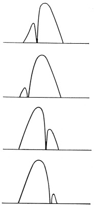
Fig. 2. Illustrating the way in which the phasing notch can be moved with respect to the peak response frequency of the filter.
Interference
The effects of interference are considerably different with reception of this type as compared with detection using the incoming carrier. A strong interfering carrier will never "capture" the detector, providing the b.f.o. voltage is large compared with all incoming signals. Interference that falls in the rejected sideband region is of course highly attenuated, a normal consequence of the selectivity. Some of the side frequencies from s signal in the rejected sideband may fall inside the passband of the receiver but they will not be intelligible; their carrier is gone and the only one they can beat with to produce audio output is the b.f.o. Since this is on a different frequency, the effect is quite similar to that from a mistuned s.s.b. signal - noise and crackles, but nothing that can be understood. This is also true of sidebands associated with an interfering carrier that falls inside the passband - beating against the b.f.o., they make only monkey chatter and tend to be suppressed by the strong b.f.o. signal. Thus the tables are turned on the interfering carrier that is stronger than the desired one.
Converting all undesired sidebands into monkey chatter means, in practice, that interference can be quite strong before it seriously degrades the desired signal. The mind is highly capable of ignoring noises of this kind and concentrating on the intelligible voice of the desired signal - much more so than if interference of the same intensity were also intelligible. Clear copy is readily possible under conditions where the desired signal would be washed out with normal-type reception.
The heterodyne from an undesired carrier falling in the passband is, of course, an important factor, although here again it simply adds a noise and does not otherwise affect the desired voice. Heterodynes can be attacked in a couple of ways. One is to use an adjustable rejection system of high selectivity, either at audio as in the "Selectoject" or "Hetrofil" or at i.f. as in the "Q Multiplier." These devices are not normally included in receivers, but can be added without too much trouble. The other is to arrange things so that either sideband of the desired signal can be selected, thus making it possible to place an interfering carrier in the rejected-sideband region; i.e., selectable-sideband reception. This means moving the phasing notch from one side to the other of the filter peak, as indicated in Fig. 2. Since this necessitates resetting the b.f.o. frequency and retuning to move the incoming carrier into the notch, it is not well adapted to quick change from one sideband to the other. This is unfortunate, but instantaneous selection requires a specialized system. With an ordinary receiver, the best that can be done is to mark the proper settings of the phasing and b.f.o. controls, or switch in padding capacitors that accomplish the same result.
Receiver modifications
We have been talking about a method of tuning, not a circuit, and using the method doesn't necessitate any changes in your receiver. However, the performance of particular receivers may leave something to be desired in a couple of respects. One is the behavior of the manual r.f. gain which was hinted at earlier. When the overall gain is changed by mean of the r.f. rather than the audio gain control there should be no change in the signal-to-noise ratio of the receiver. Nevertheless, with many receivers the signal will tend to disappear into noise as the r.f. gain is turned down, instead of both noise and signal being reduced together.
This can almost always be traced to the fact that the manual gain control operates on the first tube in the receiver. If the gain of the first tube is cut far down there is still noise generated in the plate circuit of this tube to be amplified in subsequent stages. Likewise there is noise generated in the first mixer or converter to be amplified by the i.f. These two sources of noise are almost constant regardless of the manual gain setting. So if the r.f. gain is reduced enough to keep fairly strong signals at a satisfactory level at the second detector, as compared with the b.f.o. level, weak signals may disappear into this residual noise.
Signals and noise can practically always be brought into their proper relationship, regardless of the r.f. gain control setting, by operating the first tube in the receiver "wide open" - that is, at full gain all the time. In most cases all this requires, in the way of circuit changes in the receiver, is to disconnect the bottom side of the first-stage cathode resistor from the manual gain-control line and ground the resistor.
If it occurs to you, as it probably will, to ask why the manufacturer of the receiver didn't do it that way in the first place, the answer is that he was more concerned with another problem - preventing overloading and cross-modulation from strong signals, under all sorts of conditions. This requires reducing the signal level at the earliest possible point in the receiver. You can still have that overload protection by putting in a s.p.d.t. toggle switch to select either type of operation. The whole circuit is shown in Fig. 3. A somewhat better scheme is to install a separate gain control on the first stage, which will allow using just as much gain in the first stage as conditions will permit without running into overloading effects, but this is merely a refinement.

Fig. 3. The simple change indicated by the dashed lines will improve the signal-to-noise ratio of many receivers when using the manual r.f. gain control at low. gain settings.
Incidentally, before starting to unsolder connections in the receiver, take a look at the circuit in its instruction book. Although most receivers use the simple gain-control circuit mentioned, some have more elaborate systems which may require different treatment to accomplish the same end. And before tackling any receiver, make this simple test: Set up the receiver for c.w. reception using as much r.f. gain as you can without having signals "block" or "mush up." Tune in a weak signal, set the audio volume at maximum, and then back off on the r.f. gain until the signal is no longer audible. If the noise disappears at the same time, you don't need to worry about the signal-to-noise ratio of your receiver. But if there is a lot of noise left when the signal has gone, you've got room for improvement. It is to be understood, of course, that the noise we're talking about is that generated in the receiver, not noise picked up on the antenna. Pick a quiet time, when there isn't appreciable static, for this test.
Another point: This method of reception depends a great deal on receiver stability for best-quality audio output. Although the received signal will be thoroughly intelligible even though the tuning is such as to result in an error of 100 cycles or more in the "inserted" carrier frequency, the voice does not sound quite natural with such tuning. (The effect is exactly the same as with a slightly mistuned s.s.b. signal.) The appearance of the beat note when the receiver drifts off the incoming carrier is warning enough that it is time to touch up the tuning, but this can be avoided if the receiver stability can be improved. A bit of temperature compensation on the high-frequency oscillator and b.f.o. may help, if drift is annoying.
The receiver should have a good strong b.f.o., since the b.f.o. signal at the second detector wants to be several times as strong as the strongest incoming carrier. In many receivers the b.f.o. is definitely on the weak side. This is evidenced in c.w. reception by a "blocking" or "limiting" effect when r.f. gain is run up. C.w. signals should sound clean, without any mushiness on strong signals. If a v.t. voltmeter is handy, measure the rectified voltage across the diode load resistor in the second detector circuit with the b.f.o. on and the r.f. gain down. It should be at least 10 volts and it doesn't hurt to have 25 or 30.
The b.f.o. signal can be increased in various ways, the simplest probably being to increase the voltage on the b.f.o. tube by using lower values of dropping resistance to the plate (and screen, if used). An alternative method is to use a larger value coupling capacitance between the b.f.o. and the detector circuit. In some cases it may even be necessary to couple the b.f.o. voltage to the grid of the last i.f. stage and thus take advantage of the amplification in that stage, although usually this has the undesirable feature that the actual b.f.o. voltage at the detector diode then depends on the r.f. gain control setting. A little experimenting with various methods may be needed if you find your b.f.o. to be too weak, but it will pay off in cleaner reception on both phone (by the s.s.b. method described above) and c.w. In fact, all these things are aimed at making a better c.w. receiver, which is essentially what must be done if better phone reception is to be realized.
Your receiver may or not be as good as it could be, and simple checks of this sort will help you find out. But it doesn't cost anything except a little time to try the method itself. After trying it, you may decide that the extra freedom from QRM isn't worth its price of getting used to a new method of tuning, and you may prefer to go back to the BCL variety. That's up to you, but you will at least do so knowing a bit about some of the possibilities of better communication that have been at your finger tips all along.
Notes
- Grammer, "House-cleaning the low-frequency phone bands," QST, May, 1947.
George Grammer. W1DF.