Multiband L matching network
Wide-Range natching by capacitance variation.
Making use of the reactance-variation characteristics of series- and parallel-tuned circuits as the frequency is varied provides the means for impedance matching over a wide range of frequencies without changing inductance. The tank circuit described in this article covers two bands with capacitive tuning only. Design information covering practical amateur applications is given.
Various forms of T, pi and L matching networks are becoming very popular in amateur transmitters, because of the relative ease with which coupling can be adjusted, and because of good harmonic attenuation for TVI reduction. For work on more than one band, however, it is usually necessary to vary inductance as well as capacitance in the usual circuits. This leads to tapped coils, roller coils or plug-in coils when more than one band is to be covered. This article describes a two-band L matching network, patterned on the principles of the multiband tuner.(1) This L network requires varying only two capacitors to achieve a match to a similar load on each band.
An L matching network can be of two forms, as shown in Fig. 1. Either shunt L and series C can be used as in Fig. 1A, or shunt C and series L can be used as in Fig. 1B. Each reactance of Fig. 1 is uniquely defined by the specified matching conditions, according to the relations shown in the figure, which apply for resistive loads. These relations are well known and can be easily derived.
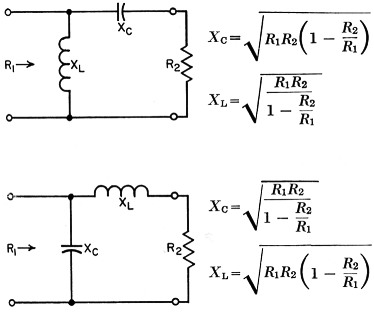
Fig. 1. Design relations for reactive L matching networks.
Now if the series arm is replaced by a series-tuned circuit and the shunt arm is replaced by a parallel-tuned circuit, the circuit would be that of Fig. 2. If we choose both the series-resonant frequency of the series arm and the antiresonant frequency of the shunt arm to lie between the lowest and highest desired matching frequencies fa and fB, respectively, then at frequency fA the circuit will be equivalent to that of Fig. 1A, and at frequency fB it will be equivalent to Fig. 1B. This is because a series-tuned circuit is capacitive below its resonant frequency and inductive above it, and the parallel-tuned circuit is just the opposite. Thus, if we properly proportion the circuit reactances in Fig. 2, we can achieve a resistive impedance match at both frequencies fA and fB.
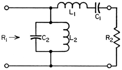
Fig. 2. Two-band reactive L matching network.
The desired matching condition could be realized simultaneously at the two frequencies fa and fB, but this would be undesirable because of harmonic response, since fa and fB are harmonically related in amateur applications. Therefore, we need to adjust the circuit constants so that the two capacitors of Fig. 2 can each be varied by a specified amount when changing from one band to another. In the relations to be given, we will let the capacitances at frequency fA be C1A and C2A, and at frequency fB, C1B and C2B, respectively. For convenience, we will assume that each capacitor is varied by the same ratio when going from fa to fB; that is, C1A / C2A = C2A / C2B. We will also make the following assumptions:
- The load impedance R2 is a pure resistance at both frequencies fa and fB. This assumption is valid if there is a low v.s.w.r. on the feed-line, or if the feedline is a resonant length and is connected to a broadly resonant antenna such as a dipole. Where the assumption is not valid - that is, where there is reactance present in the load - then C1 can be varied to tune out reactance within limits, or an additional coil or capacitor can be added in shunt or in series with the load so as to make it resistive.
- The load impedance R2 is the same at both frequencies fa and fB. This assumption is also reasonable, especially when coaxial cable is used for each antenna on each of the two given bands. Many amateurs use a vertical on the lower bands, matched to a 50-ohm coax, and a beam on the higher bands, also matched to a 50-ohm coax. The circuit can be analyzed for the general case, of course, but the result is not as simple as that given here. For convenience, we will define the following relations:
and
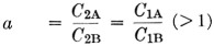
Under the above assumptions and with the parameters defined in Equation (1), the necessary reactances at the lowest frequency, fA, are given exactly by
Also from the above relations,
The latter two relations are convenient when rearranging values to fit components on hand.
For most applications the transformation ratio R1/R2 is much greater than 10, so that the quantity s in Equations (1) through (5) is very closely unity. Rm is, of course, the geometric mean between impedances to be matched, and k will normally be an integer, such as 2, 3 or 4 for amateur work where bands are harmonically related. The quantity a is chosen arbitrarily, within the limits of available tuning range of capacitors, and can be adjusted to fit particular components on hand. Choice of a = 1.5, s = 1 and k = 2, for example, gives from Equations (2) through (5):
XL1 = 1.4Rm (2a)
XC1 = 2.4Rm (3a)
XL2 = 0.357Rm. (4a)
XC2 = 0.556Rm (5a)
which are the values of reactance, at the lowest frequency fA, in terms of the geometric mean of impedances to be matched, and for two adjacent amateur bands harmonically related by 2:1.
Curves of the four relations of Equations (2) through (5) are given in Figs. 3, 4, and 5 for three values of k. To design the circuit, it is only necessary to choose a value of a, the desired capacitance tuning ratio, read off the values from the curves, and multiply these values by the desired value of Rms or Rm/s, which both are very closely the geometric mean between R2 and R1 for most applications.
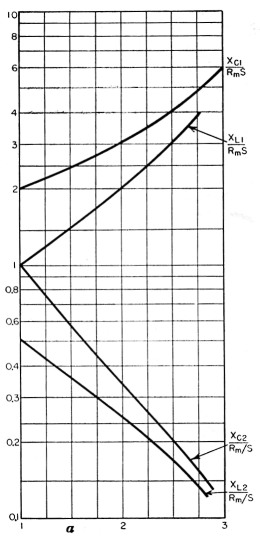
Fig. 3. Reactance values at fA as a function of a, for fB / f A = 2.
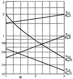
Fig. 4. Reactance values at fA as a function of a, for fB / f A = 3.
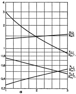
Fig. 5. Reactance values at fA as a function of a, for fB / f A = 4.
Spurious responses
It was mentioned earlier that it is desirable to vary the capacitors between bands in order to avoid harmonic response problems. While it is possible to determine the spurious responses of the circuit with a fixed value of R2, and choose the value of a so as to avoid these responses (that is, keep them from being harmonically related to either fA or fB), this analysis would mean little in the practical case. This is because the load impedance is not a pure resistance R2, except possibly at the harmonics themselves, because of the fact that an antenna and feedline comprise the load. Therefore, it is better to choose the value of a arbitrarily, within limits, and determine in the actual case with an absorption wavemeter or field strength meter whether or not the harmonic output is excessive. Tests with this circuit have shown that as long as the tuning ratio a is greater than about 1.3, the spurious responses will not be harmonically related to either fA or fB for the most commonly used antennas.
A design example
Suppose we wish to match a parallel 813 final amplifier to a 50 ohm load, which load is resistive and the same on two bands: 3.5 and 7.0 Mc. Suppose we wish to operate the tubes at 2000 volts plate voltage and 400 ma. plate current. We should then have a load resistance of about 2000 /(2 × 0.4) = 2500 ohms. The transformation ratio R1/R2 = 2500/50 = 50, so that parameter s in Equation (1) is very closely unity. The geometric mean between 2500 and 50 is Rm = √(2500 × 50) = 354 ohms, and k = 7 / 3.5 = 2. We will choose a = 1.6 to insure that spurious response is well away from harmonics. From Fig. 3 (for k = 2) at a = 1.6, we find
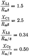
Since Rm = 354 ohms and s = 1, then
XL1 = 1.5 × 354 = 531 ohms
XC2 = 2.5 × 354 = 885 ohms
XL2 = 0.33 × 354 = 117 ohms
XC2 = 0.50 × 354 = 177 ohms
which are the reactance values at the lowest frequency of 3.5 Mc. The corresponding values of inductance and capacitance are then
L1 = 24.1 µH
C1A = 51 pF
L2 = 5.3 µH
C2A = 256 pF
At the higher frequency, 7.0 Mc., since a = 1.6 by choice, C1B = 51 / 1.6 = 31.9 pF and C2B = 256 / 1.6 = 160 pF. So for C1 we would choose a capacitor tuning from about 30-50 pF and for C2 a capacitor tuning from about 150-250 pF (the latter could be 100 pF variable with 150 pF of fixed capacitance across it). The complete circuit would be as shown in Fig. 6.
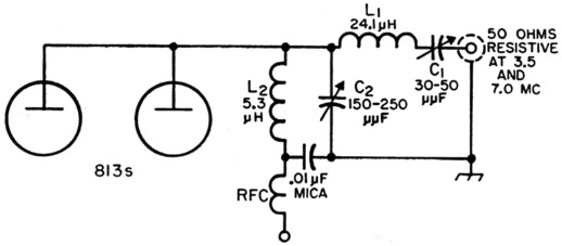
Fig. 6. Circuit of a two-band L matching network for 2500 to 50 ohm transformation at 3.5 and 7 Mc.
As is evident from Fig. 6, this circuit has one additional advantage over the customary pi network, that being a high-quality r.f. choke is not required, and series feed can be used. For other bands, such as 14, 21 and 28 Mc., the design procedure would be the same, requiring a change in coils and capacitor settings if more than two bands are to be covered for the same load impedance.
This circuit is by no means a universal replacement for pi or coupled circuits when very high transformation ratios are to be handled. Whenever the geometric mean between R1 and R2 is high, it will be found that L1 becomes quite large and C1 quite small, so that this circuit is not ideal for all matching problems. It can be used in many transmitters, however, where transformation ratios are not too high and reactance in the load is not too severe. Theoretically, it is possible to gang C1 and C2, but this would preclude tuning out reactance in the load such as inevitably appears in varying degree, and still maintain an optimum match, so it is recommended that C1 and C2 be left as separate controls. As with most pi networks, the best tuning procedure is that which uses antenna current (output) as a basis for tuning, although the circuit given here is not difficult to tune using only plate current as an indicator. A current dip at resonance will be found as C2 is varied.
The same principle used here can be applied to other arrangements of matching networks, such as the pi, but the number of components required becomes high (3 coils and 3 capacitors), and this disadvantage is not offset by the increased advantages obtained, such as the ability to handle a wider variation in load reactance. It is also possible to have a parallel-resonant circuit for the series arm and a series-resonant circuit for the shunt arm, for which the design relations are quite similar.
Notes
R.W. Johnson, W6MUR.