Grounded-grid tetrode kilowatt
In this article you'll find a description of a high-power amplifier, designed both for c.w. and as a linear for s.s.b. or a.m., in which either 4-125A, 4-250A or 4-400A tubes can be used. Making full use of the output of any "100-watt" transmitter for driving, it's a grounded-grid tetrode kilowatt.
After operating a transmitter in the 100-watt class for a few years, the desire for greater power became more pressing as the DX became a little more elusive and the competition keener. The particular transmitter, a B & W 5100, was quite convenient to operate and so we wanted to continue to use it - as a driver for a higher power final amplifier if possible. But in order to avoid neutralizing and to minimize the possibilities of TVI, tetrodes were the natural choice for power tubes for the new amplifier. However, if the tubes were grid-driven in the usual way, either the output of the driver would have to be reduced, or some of its output would have to be dissipated in a dummy load.
Neither of these alternatives was attractive, nor was the further thought of an associated high-Q grid circuit that would require tuning. Cathode drive, available statistics seemed to indicate, would require extremely high driving power for the tube types available, but with most of the driving power contributing useful output. However, there is some question as to the desirability of operating the tubes triode connected, because of the dissipation limits of the control grid. The most attractive solution seemed to be to use cathode drive with the tubes tetrode connected and with d.c. voltages on the screen and the control grid to establish the operating parameters.
C.w. operation was the prime requisite, with linear operation for single side band next in importance. At the time the final was being considered, operation as an a.m. linear at full input also seemed desirable, establishing a further requirement for roughly 660 watts of plate dissipation. Therefore a pair of 4-400As was selected, although 4-125A or 4-250A tubes would have been equally adaptable without the a.m. requirement.
In the interests of convenience and operating simplicity, we planned to attempt to devise some method of cathode drive that would not require tuning. Fortunately, before construction began B & W made available their ferrite-cored bifilarwound filament chokes, one of which is incorporated in the amplifier. No low-capacitance filament transformer is required, and the input is untuned. The pi network in the driver loads noncritically over a wide range of frequencies on all bands from 80 to 10 meters, inclusive. As an example, v.f.o. operation across the first 100 kc. on 20 meters is possible without retuning the driver, and with no significant loss in excitation. With an antenna essentially flat over the same range, the amplifier does not need to be redipped either. This makes the system very desirable for DX and contest work.
Results
The operation of the amplifier has been extremely satisfactory to the author. It has complicated station operation not at all, since band switching is almost as easy as with the small transmitter alone. No TVI difficulties have been encountered although a low-pass filter has not been used, but probably it would be well to add one as a precaution, particularly in those areas with low TV signal strengths. On-the-air reports have been indeed gratifying, and there is the additional satisfaction of knowing that a good percentage of the driving power is getting into the antenna.
Construction
The amplifier is mounted on a standard 12 × 19 inch aluminum rack panel and a 13 × 17 × 4 inch aluminum chassis. The latter is spaced from the panel by six ½ × 2 inch spacers, tapped for 10-32 screws. Top shielding consists entirely of do-it-yourself aluminum available at hardware stores. The framework is constructed from ¾ × ¾ inch angle stock, the front and sides are sheet stock, and the top and back are perforated sheet stock. Four 1¼ inch wide angles are cut from the angle stock to form mounting feet for the four 7_1/8 inch uprights, which are butted to the top frame. The top frame is made from four pieces of angle stock which have been mitered. Four 1¼ inch pieces of angle stock are used to join the uprights to the top frame. Holes are tapped in the uprights and top frame to fasten the joining pieces, and also for attaching the sheet stock. The resulting frame is strong and rigid, and while the sheet stock may seem quite light in gauge compared to thicknesses ordinarily used in radio chassis work it affords a rigid shield with more than adequate strength, since it acts only as a shield and has no structural function.
ln order to reduce the over-all height of the shield by 1½ inches, the B & W pi-network tank coil was modified slightly, with no detriment to its operation. The ten-meter ribbon inductor was carefully removed from the assembly and, looking at the rear, the left-hand termination of the coil was bent in the opposite direction from its original position. Thus the coil extends to the rear instead of above the assembly. An inch or so of the ribbon on the right-hand side was uncoiled and a right-angle bend made so that the coil terminates at the unused hole in the upper right-hand corner of the rear ceramic plate. It may be necessary to remove an inch or so of the ribbon and redrill the coil for a good fit. A jumper of half-inch brass or copper strip runs from this terminal to the switch point where the coil was originally connected.
A continuous length of half-inch brass strip is used for the lead from the coil assembly to the vacuum tank capacitor and the plate blocking capacitors. The plate sides of the blocking capacitors are mounted on a bracket attached to the top of the plate choke and extending midway between the tube plate caps. Connection is made to the plate caps by heavy copper stranding. The small bottom insulator on the plate choke was removed and replaced by the 500-pf. by-pass capacitor. The vacuum variable is mounted vertically, and is driven by a right-angle drive over the chassis from the Groth counter dial on the front panel. The output coax connector is mounted above the chassis on an aluminum bracket, and is connected to the coil assembly by a short piece of half-inch brass strip. A connection midway along this strip goes through a feed-through insulator to the loading capacitor under the chassis.
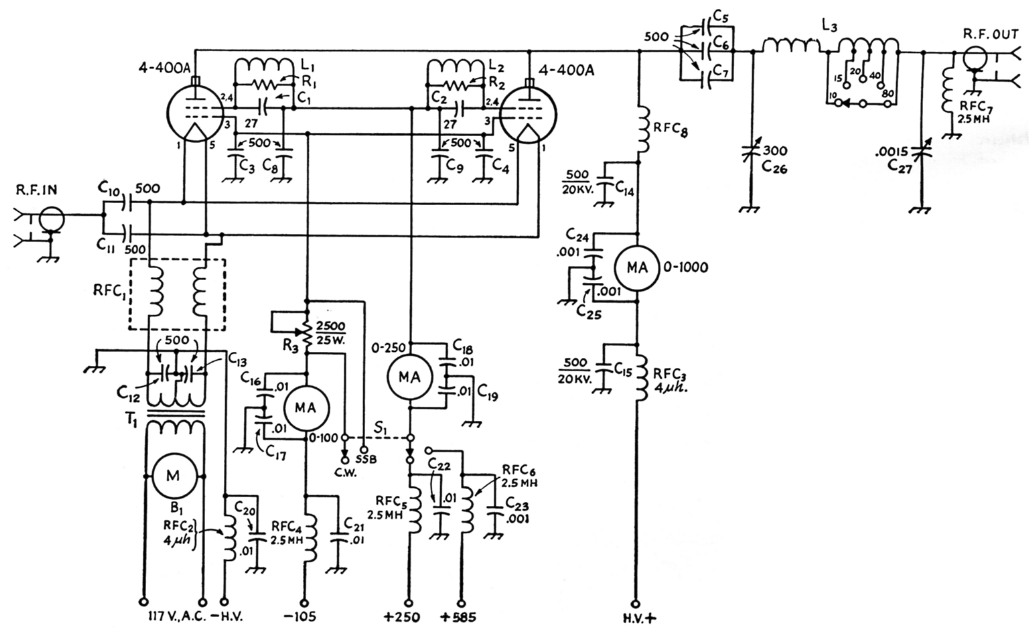
Fig. 1. Circuit of the parallel 4-400A amplifier.
Capacitances below 0.001 µF are in pF.
| B1 | Blower motor (see text). |
| C1,C2 | mica (20 to 50 pF satisfactory). |
| C3-C7 inc. | 500 pF ceramic, 5000 V (Centralab 858S). |
| C8-C13 inc. | 500 pF ceramic, 20 kV (Sprague 2ODK-T5). See text. |
| C16-C22 inc. | 0.01 µF disk ceramic, 1600 V. |
| C23-C25 inc. | 0.001 µf. disk ceramic, 6000 V. |
| C26 | 300 pF vacuum variable (Jennings UCS). |
| C27 | 1500 µF variable, 0.03 inch spacing (Cardwell PL-8013). |
| L1,L2 | 4 turns No. 12 spaced wire diam., wound over R1 and R2. |
| L3 | Tapped tank inductor; 3.5 Mc.: 13.5 µH; 7 Mc.: 6.5 µH; 14 Mc.: 1.75 µH; 21 Mc.: 1 µH; 28 Mc.: 0.8 µH (B & W 850). |
| R1,R2 | 100 ohm, 2 watts, carbon. |
| R3 | 2500 ohm 25 watt rheostat. |
| RFC1 | Special bifilar filament choke (B & W type FC30). |
| RFC2,RFC3 | 4 µH (National R60). |
| RFC4-RFC7, inc. | 2.5 µH (National R100S). |
| RFC8 | National R175A. |
| S1 | D.p.d.t. wafer, separate ceramic section for each pole. |
| T1 | Filament transformer, 5 V, 30 A. |
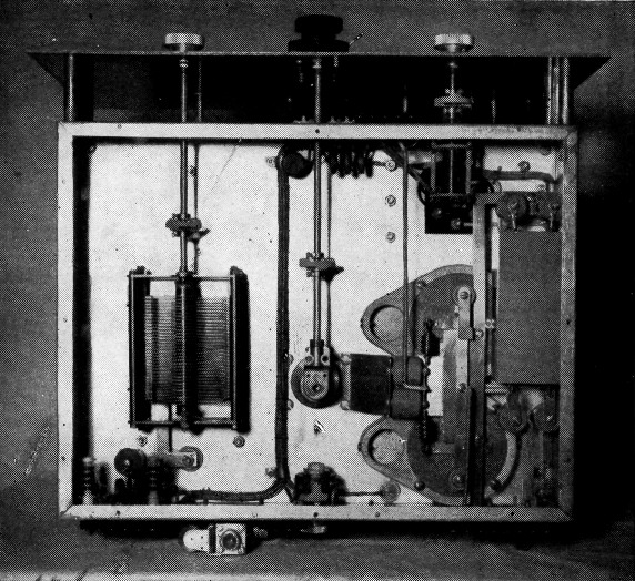
The tapped tank inductor and variable vacuum capacitor are becoming familiar sights in the "de luxe" high-power amplifier. The two 4-400As in this layout provide ample plate-dissipation capability for operation as an a.m. linear at a kilowatt input.
The counter dial drives the vacuum variable. Controls at the left are (top) the band switch and (below) the pi-network loading capacitor. Control-grid, screen, and plate currents are measured by the three panel meters. The knob below them operates a "c.w.linear" switch that changes grid bias and screen voltage according to the type of operation.
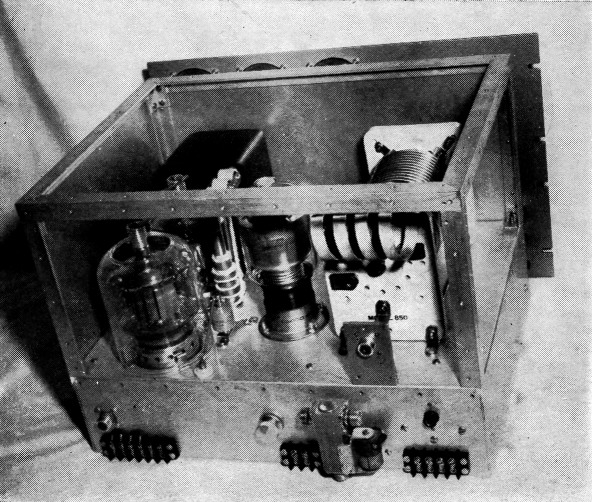
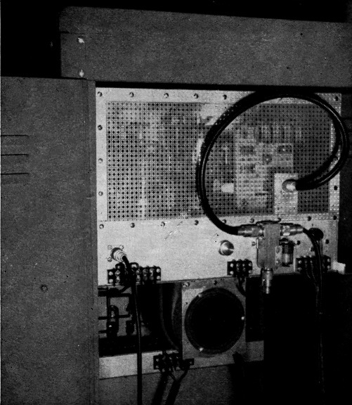
Some of the layout details are shown in this rear view. The knob at the center of the chassis wall operates the variable resistor used as a grid leak in c.w. operation. Plate voltage is introduced through the high-voltage connector at the right. Other voltages go to the connection-blocks along the bottom edge.
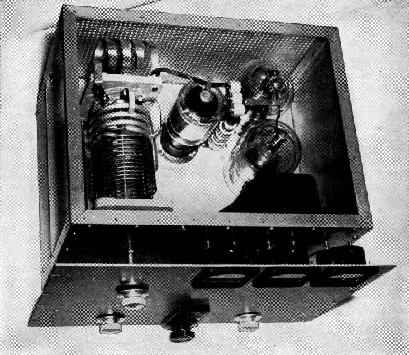
The use of brass strip for r.f. connections around the tube sockets makes for neat "wiring" as well as low-inductance ground returns. The filament choke is in the rectangular can mounted on the chassis wall next to the tube sockets. The variable capacitor is for control of loading.
Beneath the chassis, the Eimac Air-System sockets are mounted with their filament terminals adjacent. All element interconnections on the tube sockets are made with %-inch brass strip. The filament choke is mounted on the side of the chassis, and is connected to the tube sockets and filament transformer by short lengths of No. 12 wire. The blocking capacitors at the filament end of the choke, as well as the by-pass capacitors at the cold end, are connected to the choke with leads as short as possible. The lead from the input coax connector is 3A-inch brass strip, as is also the ground return from the bypass capacitors. All r.f. grounds are terminated at a 2-inch wide piece of brass shaped somewhat like a "T," with the arms of the "T" extending over the sockets. The foot of the "T" is fastened under two of the mounting bolts for the vacuum variable.
All d.c. leads are TV high-voltage wire, shielded with copper braid. Bypassing is used at the terminal strips for meter connections at the front of the chassis, and chokes and bypassing are used at all d.c. power terminals at the rear of the chassis. In the rear view, the terminal strip to the left (immediately below the r.f. input connector) is for connecting 117/230 volts a.c. to the filament transformer, and to supply 117 volts a.c. for the blower motor. The knob in the center is for R3, and the terminal strip to the right and below it is for the antenna relay coil. The terminal strip at the far right, below the Millen high-voltage connector, is for the two screen voltages, bias voltage, and common connections.
In the front view, the meters from left to right are for plate, screen and grid current, respectively. The upper left-hand knob switches the pi-network coil, and the knob below it is for the loading capacitor. The Groth counter dial in the center tunes the vacuum variable, and the remaining knob is on the c.w.-s.s.b. switch.
Circuit Notes
When the amplifier was first tested, a potent 190-Mc. parasitic appeared during operation as a linear amplifier. Its frequency remained unchanged regardless of the addition of parasitic chokes or traps in the normal positions in any and all element leads. A grid-dipper revealed that the grids, when disconnected from all circuitry, seemed to be floating at the parasitic frequency, which could also be "dipped" in the screen and cathode circuits. An Eimac Engineering Newsletter provided the solution. Briefly, the parasitic trap C1R1L1 loads the parallel-resonant parasitic circuit formed by the screen-cathode capacitance and the lead inductances of the screen and cathode, while the 500-µ4 capacitor continues to function normally as a low-frequency bypass. No other means of parasitic suppression were needed, nor is neutralization in any form required. The amplifier is completely stable at all operating frequencies.
Initially, disk ceramic capacitors were used in the cathode circuit for blocking and bypassing, but the driver loading was found to be critical in the 10- and 15-meter bands even though the capacitor leads were kept short. After replacing the disks with the specified capacitors, the loading was no longer critical, even with different lengths of coax between the driver and amplifier.
The length of the coax should be as short as practicable; a length of 6 feet of 72-ohm cable gives satisfactory operation.
Tuning
Tuning is much the same as in any conventional amplifier, although at least one important precaution must be observed: Full driving power should not be applied without plate voltage on the amplifier, or without an output load. The resultant high grid current would damage the tubes. Screen voltage may be removed for tuning, but a d.c. path from screen to ground must be maintained; otherwise the grids will be forced to dissipate the entire driving power.
During initial tune up, it is suggested that reduced driving power and reduced plate voltage be used. On c.w., adjust the antenna coupling for maximum output, and with full plate voltage applied adjust the bias control, R3, and the driving power for desired plate and screen currents. As a linear, adjust the antenna coupling for maximum output (with single-tone input), and then reduce the driving power until no grid current flows. The output of any of the 100 watt class transmitters is more than adequate to drive the amplifier to the maximum legal input on all bands between 80 and 10 meters. As a linear, the amplifier takes approximately 75 watts of drive.
After initial adjustments, a simple tuning chart permits quick band change without a lot of key-down operation, since there are no critically tuned circuits.
The completed amplifier installed in the rack, with shielding and blower mounted in place. As suggested in the text, a smaller blower can be substituted to make the unit completely self-contained, since there is ample space available in the chassis.
Power Supply
Since little published information is available on screen and bias voltages for the type of operation selected, the choice was made on the basis of highest efficiency on c.w. and best linearity on s.s.b. for the available plate supply of 2500 volts. Higher efficiencies could undoubtedly be obtained with higher plate voltage, but at greater cost in power-supply components. Fortunately, a common fixed bias of 105 volts from an 0C3 serves on both c.w. and s.s.b., with additional bias on c.w. furnished by R3. A screen supply of 250 volts with this grid bias provides high efficiency on c.w. with full plate input, a screen current of 90 ma., and a grid current of 20 mA for the two tubes. The bias cuts off the amplifier completely, and keying is accomplished in the driver. Reasonably good screen supply regulation is needed, because under key-up conditions plate current would flow if the screen voltage increased materially.
For linear operation the resistor bias is switched out and a screen voltage of 585 volts switched in. Resting current is approximately 180 mA, and no grid current is drawn under full peak-envelope input. Screen current is 36 mA at peak input. The screen voltage for linear operation is supplied from a VR string which is connected across the 2500 volt d.c. supply in series with a 50,000 ohm resistor. The screen voltage is established for the proper resting current by changing the VR tube combinations. Variation from 500 to 850 volts is possible without the necessity for changing the series resistor. A 50,000 ohm bleeder is used as well, and the VR string remains across the supply in c.w. operation for improved regulation.
Cooling
Some form of blower should be used to keep the tube seals within temperature ratings in order to obtain full life from the tubes. Originally, a smaller, higher-speed unit was contemplated so it could be mounted on the chassis or at the rear of it. However, blowers do not seem to be too readily available even in the larger cities, and they are not low in cost. In the interests of getting on the air, a surplus unit was purchased which was physically too large to be placed in the chassis. It is mounted on the bottom plate by means of a piece of ¾ × ¾ inch aluminum angle and a piece of 1/8 inch thick aluminum, and must be removed before the amplifier can be withdrawn from the rack. If the amplifier were to be used in a table-top cabinet, the smaller variety of blower would be the best solution; it could easily be accommodated below or on top of the chassis.
Eimac Air-System sockets were used because of their mechanical excellence and the fact that air is channeled exactly where it is needed. For those who might find the cost prohibitive, a number of good designs using less expensive sockets have appeared in QST in recent months. As for pressurizing the chassis, no special pains need be taken other than to cover any large unused holes, such as those punched in the ends of many chassis for rack panel brackets.
David Muir,W9DZY.