Variable band width Q multiplier
Continuously variable selectivity for the receiver.
Since its appearance in one form or another in several kits and communications receivers, the Q multiplier is no stranger to most amateurs. If you are not already using one to improve your receiver performance, this article tells how to build and adjust one that is continuously variable in its band width. Some good construction hints are included.
The Q multiplier enjoys a well-deserved popularity these days, for several reasons. It is an outrigger device that can be added to an existing receiver with practically no receiver modification, an important factor these days when one must consider the resale value of receivers. In its most popular version it will provide either a "peak" for c.w. reception or a "null" for phone or c.w. work. The peak or null can be moved across the pass band of the receiver. As its name indicates, the Q multiplier is a device that "multiplies" or increases the Q of a circuit many times, and the high-Q circuit is then used as an equivalent parallel-tuned circuit (peak) or a series-tuned circuit (null) across an i.f. amplifier stage. It is an application of the principle of regeneration, but it is a stable and readily-controllable one.
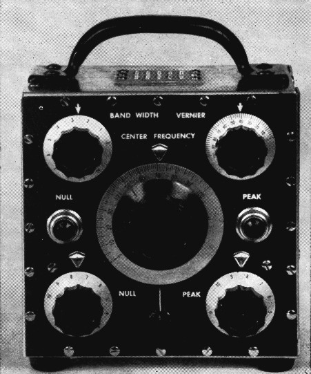
Black crackle finish on the panel and the' generous use of decals dress up the Q multiplier. The panel is 6 inches square.
Circuit
The specific circuit described here (Fig. 1) provides for the peak and null functions and, also, variable band width in the peak position. This is the basic circuit devised by Villard,(1) but a few minor changes have been made for operating convenience.
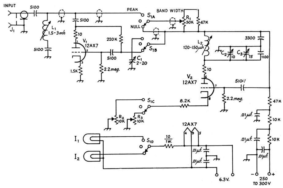
Fig. 1. Schematic diagram of the Q multiplier. Resistors are ½ watt unless specified otherwise. All capacitances are in uuf. unless specified otherwise.
| C1 | Air trimmer (Hammarlund MAC-20). |
| C2 | 10 pF variable (Johnson 167-1). |
| C3 | 75 pF variable (Johnson 167-4). |
| I1,I2 | 6 volt pilot lamp. |
| J1 | U.h.f. cable receptacle, SO-239. |
| L1 | Adjustable cup-core inductor (North Hills 700A). |
| L2 | Adjustable cup-core inductor (North Hills Type 700 form, close-wound with 45 turns No. 32 d.s.c.). |
| S1 | 2 gang 4 pole 6 position (3 positions used) rotary switch. |
To make tuning easier, a 10-to-1 electrical vernier, in the form of a 10 pF variable shunted across the 75 pF main tuning capacitor, is provided. This vernier ratio seems optimum for the writer's tuning practices. Other operators have different choices; some may wish to omit the electrical vernier and use a reduction drive on a 75 pF tuning capacitor. Regardless of the control method used, the main tuning capacitor (and vernier, if used) should be mechanically rigid, with a minimum of slop and end play in the bearings.
As connected, the heater and plate circuits of the Q multiplier are always "live" when the receiver is turned on. To indicate clearly what function the multiplier is switched to, two pilot lights are used. One is lighted when the Q multiplier is switched to PEAK, the other when the multiplier is switched to NULL. Both pilots are out when the switch is in "off" (center) position.
To prevent intercoupling with other circuits in the receiver, the plate and heater circuits of the multiplier are isolated with some care. Plate isolation is obtained with a two-section RC filter consisting of two 10K resistors and three 0.01 µf. disk ceramic capacitors. Heater bypasses are used, and to eliminate hum modulation resulting from heater-cathode leakage and diode action, the heater center tap is biased approximately +40 volts with respect to ground.(2) The Q multiplier will work excellently, however, with the heaters connected in any conventional fashion.
Construction
The case for this instrument is made from a Seezak 6 × 6 × 4 inch expandable aluminum chassis. Rail tongues are backed with 3/8 × 3/32 inch strip brass, held in place with 3-48 flat-head machine screws, and the tongue bosses are drilled and tapped 6-32. This permits assembly and disassembly for servicing without either wrestling with the sheet-metal parts or stripping screw threads in thin sheet metal. The interior shelf is a piece of 4-inch wide Seezak rail, shortened to just under 6 inches long, and equipped with a flange on both ends. Both flanges are backed with brass strip, to increase strength and screw-holding capacity.
The front panel is finished in black crackle enamel to reduce glare and reflections. Panel markings are made with decals (" Tekni-cals "), which are protected against wear by coating them with clear lacquer after thorough drying (24 hours or more). Small ventilating grilles are mounted in the centers of the top and bottom rails, in the upper center of the back plate, and in the front center of the interior shelf. These grilles are made from Seezak type MP-12 mounting plates by drilling out the holes to %-inch diameter and lightly countersinking to remove burrs. A handle (Stanley No. 3 door pull) is mounted on the top with 10-32 oval-head rack screws; and four husky rubber feet are attached with 6-32 screws to the bottom corners. The ventilating grilles and rubber feet assure good air circulation no matter where the instrument is placed, so that thermal stabilization is rapid and frequency drift minimized.
Mechanical assembly is quite simple, and the exact arrangement of parts is not critical. They must, however, be firmly anchored in place, so that pressing on the panel, or any other part of the case, will not change the tuning.
To insure that the components stay in place, liberal use is made of tie points, and shielded leads are anchored by soldering to lugs. Wherever a lead passes through the interior shelf, the hole is protected by a rubber grommet. A tube shield is placed over the 12AX7 to act as a mechanical hold-down. It is not electrically necessary, and any other type of hold-down can be used if preferred. Because of repeated unhappy experiences with the screwdriver slots in core screws of coils, each core screw is fitted with a 4-40 hex nut, held in place with solder. This permits tuning the coils with a hex socket wrench, which stays in place, instead of a screwdriver, which not only tends to slip out of the socket but also usually splits out the slot in a short time.
The power connector and the input jack are mounted on the rear panel below the shelf. Shielded leads are used between the bandwidth control, coils and switch. The shielded lead to the bandwidth control runs through the rubber grommet at the lower right-hand corner of the shelf.
Using the multiplier
Theoretically, the Q multiplier can be connected across any coil of the receiver i.f. amplifier, and it will work after a fashion if shunted across any grid or plate coil tuned to 455 kc. (in this case). For best results, however, the Q multiplier must not be overloaded. This should be obvious when it is remembered that a tuning fork will vibrate at any frequency if driven hard enough. So will an iron anvil!
The preferred electrical position for the Q multiplier is in the plate of either the mixer or the first i.f. stage. The connection can be made with a short length of shielded wire or, preferably, RG-58/13 coaxial line. Connect one side of a 0.01 µF disk ceramic to the plate of the mixer or first i.f. tube and connect the other side of the capacitor to the inner conductor of the coax. Ground the outer conductor of the coax to the receiver chassis close to the tube socket. Power for the Q multiplier can usually be "borrowed" from the receiver at the accessory socket, since the plate current demand is very small and the required heater current is only 0.3 ampere.
Before connecting the Q multiplier to the receiver, check the receiver i.f. alignment, so that the receiver functions normally with the Q multiplier disconnected. The circuit the multiplier is to be connected to may require a slight touching up.
When the signal cable and the power connections are completed, and the receiver is known to be functioning normally, remove the top of the Q-multiplier case, to make the alignment adjustments accessible. Set switch S1 at "off ", tune in a steady phone signal. Center it in the receiver i.f. pass band, using the S meter to insure proper tuning.
Now adjust the input coil, L1, for maximum signal. This insures that the receiver will function normally whether the Q multiplier is connected or not.
Next, center the center-frequency and vernier dials, set the null depth control to center scale, and turn the function switch to NULL. Adjust coil L2 for minimum signal (lowest S reading). Then, adjust the null depth control R3 for lowest signal level, and reduce it still further, if possible, by fine adjustment of L2. This adjustment removes the carrier and the low frequency side bands on each side of it, giving phone signals a tinny and overmodulated characteristic. Keep the BANDWIDTH control at minimum resistance during these preliminary adjustments.
Leaving the tuning unchanged, switch the function to PEAK, and advance the peak height control R2 until a squeal is heard. The oscillating Q multiplier is now beating with the incoming carrier. Back off on the height control until the squeal stops, and then adjust trimmer C1 for maximum signal, as indicated by the S meter or the "boomiest" bass response. The PEAK and NULL settings now coincide in frequency.
After checking operation with a number of signals, replace the top on the cabinet, and the Q multiplier is ready for use.
Troubles likely to be encountered in aligning a Q multiplier are few, and their correction usually is quite simple. Other than wiring blunders, most common troubles are bad tubes and parasitic oscillation. A bad tube is suggested when the maximum adjustments of PEAK and NULL are at widely differing settings of the null and peak controls. Replacement of the tube by one in which the two triodes are more nearly alike in characteristics will remedy the trouble. Parasitic oscillation is evidenced when signals are garbled at all positions of both controls. The oscillation is usually at a high frequency, such as 75 to 100 Mc., and is eliminated by inserting resistors in series with one or both tube plates. The 10 ohm resistors shown in Fig. 1 are usually adequate, but this value can be increased considerably, if necessary, without impairing any useful function of the device.
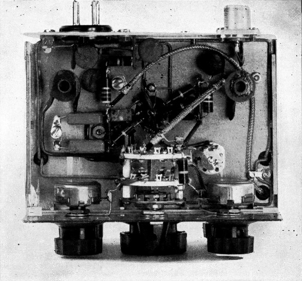
A top view of the Q multiplier with the top and side plates removed. The rear plate is a 6 inch square of aluminum, similar to the front panel. The shelf is mounted about 2 inches up on the panel.
The Q multiplier does exactly what is claimed for it in the original description.(1) In the NULL position, it provides a slot of adjustable depth to about 30 dB, with a 6 dB width of about 0.1 per cent of the intermediate frequency. This slot is tunable across the i.f. pass band. It is a simple slot, not a combination of slot and peak as with a conventional crystal filter.
In the PEAK position, with the BAND WIDTH setting at a minimum (zero series resistance), the multiplier provides a peak, of approximately the same width as the null slot, with height adjustable through a range of about 30 dB. This peak, just like the slot, is tunable across the i.f. pass band.
Increasing the band width, by means of the BAND-WIDTH control (not a part of Villard's unit), broadens the tunable peak somewhat, increasing the intelligibility of phone signals by retaining more of the side bands. This control operates most conveniently when the resistor is quasi-logarithmic, and was made so by paralleling a 50,000-ohm "logarithmic" potentiometer (Ohmite type CA) with a 47,000-ohm fixed resistor. With about 20,000 ohms in series, the Q multiplier might as well not be there, as the broadening of the pass band due to the series resistor just about matches the sharpening contributed by Q multiplication.
As preliminary tests will demonstrate, the Q multiplier tunes very sharply, even with the 10-to-1 electrical vernier here provided. Operation is logical, simple, and straightforward, but, like riding a bicycle, skillful operation requires some practice.
Because there is no interlock between the controls of the Q multiplier and those of the receiver, the Q multiplier can be used in conjunction with other band-narrowing devices, such as a crystal filter, a Q5-er, or even one or more additional Q multipliers, which can be connected in other i.f. stages. A receiver with a Q multiplier in the mixer plate and others in the plate circuits of each of three following i.f. stages will be perfectly stable, and all of the Q multipliers will function, but you will need more arms than the Hindu goddess Kali to operate them all!
Other frequencies
The Q multiplier here described is designed for operation at 455 kc. Quite obviously, as the operating principles are sound, it can be made to work at almost any other frequency. Unfortunately, however, its utility is not the same at all frequencies. The Q multiplier is substantially a percentage band-width device, the effective percentage being very roughly 0.1 per cent of the intermediate frequency.
If we make a Q multiplier to operate with a 50 kc. i.f. system, we will have a tunable slot approximately 50 cycles wide. If we switch to PEAK at 50 kc., using commercially available tuned circuits, the resultant Q at maximum peak setting is in the higher thousands, and the circuit rings so badly that we can't be sure whether or not the carrier is being keyed. It is for these reasons, among others, that the Hallicrafters SX100 uses a T-notch filter, in place of a Q multiplier, in the 50 kc. i.f. amplifier.
As we increase the i.f., the peak and slot width are increased proportionately, so that at 3.5 Mc. we can just about peak or slot an entire phone transmission.
Notes
- Villard and Rorden, "Flexible selectivity for communications receivers," Electronics, April, 1952.
Villard also developed the well-known "Selectoject." - Mr. Ives has rewired all of his receiving equipment (SX-62, NC-88, Q5-er, homemade portable) to put a positive bias on the tube heaters. He finds that it reduces hum and seems to extend tube life. - Ed.
Ronald L. Ives.