A compact all-band antenna
Advanced techniques for the modern amateur.
This article should be read carefully by all amateurs interested in the fine points of antenna design. The startling innovation disclosed here for the first time is proof positive that nothing is impossible for an amateur with enough imagination and determination.
With the ever-increasing complexity of contemporary amateur radio, as evidenced by available all-band transmitters and receivers for home and mobile work, has come a demand for packaging the gear in ways that will occupy a minimum of space. This process is often referred to as "miniaturization," and great strides have been made in some directions. One notable achievement has been the introduction of the so-called "external-anode" vacuum tube, which saves space by eliminating the vacuum outside the anode and thus the need for an envelope of some kind. Another good example of miniaturization has been the more widespread use of the higher frequencies, where smaller coils and capacitors can be used than on the lower frequencies. Transistors and other applications of semiconductor technique permit the design of compact equipment.
However, there is one area of amateur radio that still remains a fruitful field for miniaturization, and that is antenna design. Referring to such standard works as the ARRL Antenna Book, one finds that the same formula for a half-wavelength antenna(1) has been carried for years, with apparently no thought being given to its further development or simplification. Band-switching transmitters (made compact by the techniques outlined in the first paragraph) have increased the demand for suitable all-band antennas, preferably fed with coaxial line, but up to the present time the approaches to a solution to the problem have been rather primitive, to say the least. Increases in population over the past pentad have crowded the country to the point where many amateurs are forced to live in small dwellings and apartments that offer no room for the old-fashioned types of antennas or even for the newer all-band types, and something should be done about it.
Something can be done about it. The present approach to the all-band problem is to use a multiplicity of half-wave-length antennas based on the old formula' and feed them with a common transmission line, or to use a single antenna with "traps" in it. The trap idea is noteworthy but it has not been carried far enough.
Ferrites
Ordinary a.m. broadcasting uses the frequencies between 535 and 1605 kc., and old timers may recall that originally large outdoor antennas were required for satisfactory reception. However, modern technique in broadcast reception calls for a small "Loopstick" that can be installed inside the receiver. The heart of the Loopstick is a core of high-permeability ferrite, and it is to the credit of the broadcast engineers that they immediately appreciated the potentialities of the material and applied it to their receivers. Why no one but the writer has seen fit to apply it to amateur frequencies must forever remain a mystery.(2)
A "trap" antenna using ferrite cores in the coils offers many interesting possibilities. The properties of the ferrite are such that the antenna is all coil; you can visualize this as a trap antenna compressed by exerting pressure at the ends. The sketch in Fig. 1 shows an all-band antenna (80 through 10 meters) based on this principle. Including the weatherproof housing, the all-band antenna occupies a volume of not more than one foot in diameter and four feet long. Using a simple broadband matching transformer with the same ferrite core, a suitable match for 52 ohm coaxial line can be obtained, with the s.w.r. running not more than 1.3 over the entire range and dropping as low as 0.77 at some points.
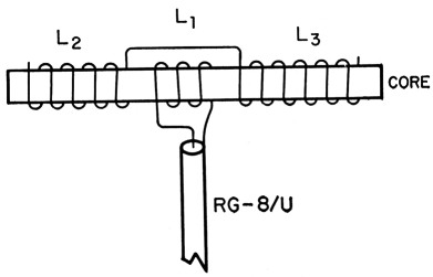
Fig. 1. The compact all-band antenna uses a ferrite core measuring 3 inches in diameter and 3.6 feet long.
L1 5 turns No. 10 Formvar, close-wound.
L2,L3 40 turns ¼ inch copper tubing, ¼ inch between turns. Spacing between coils is ½ inch.
Mounting the prototype ferrite all-band antenna at the top of a 50 foot flagpole brought excellent results over a period of several months. It was found that moving the antenna to the lower altitude of 30 feet gave poorer signal reports, indicating that the height of the antenna was a controlling factor in its performance.
The image principle
While pondering over the problem of the amateur who isn't blessed with a 50-foot flagpole in front of his terrace, the principle of the antenna "image" was recalled. This is explained in any good textbook on antennas; briefly it means that every antenna has an "image" directly beneath it in the ground, and it is the combination of the effect of the antenna plus the effect of the image that gives the antenna most of its directional properties. Conjecture as to the location of the image when the antenna proper was buried under the ground resulted in taking down the ferrite antenna from the flagpole and burying it 5 feet under the ground. It loaded the transmitter in the same way, and the s.w.r. checked out to be nearly the same as before. Examining the space above where the antenna was buried disclosed that the maximum field intensity existed 5 feet above the ground, indicating that the buried antenna did indeed have an image above the ground! Inspired by this discovery, the antenna was buried 30 feet below the ground. Raising and lowering the field-strength meter by means of the flagpole rope, the area of maximum intensity was found at 30 feet above the ground, further confirming the earlier finding. At 50 feet below the ground a very hard rock formation was encountered that prevented further experimentation at this location, but the signal reports continued upward and the performance was every hit as good, if not slightly better, than the performance had been when the antenna had been 50 feet above the ground.
Using the antenna for receiving for the first time, it was noticed that all c.w. signals came in on the other side of zero beat to what was usual for the receiver. After a little cerebration the reason became apparent: one should expect image signals with an image antenna. This works no real hardship on the operator, once he has realigned his receiver to cope with these slightly different signals.
This sketchy report is offered to the amateur fraternity in the hope that some of the remaining parameters of this antenna will be determined. For example, it is predicted that if the antenna is buried under a house that uses radiant heating the efficiency of radiation will be improved, since a good low-resistance ground system is always desirable. Operators interested in using the antenna as a vertical should, of course, raise a radial system a foot or so above the surface of the ground, although in some localities this may present a problem for pedestrians. If the antenna is buried deep into the side of a cliff, the radiation angle will be lowered and a measure of directivity will be obtained in the direction perpendicular to the cliff face. The radiation angle is then equal to 90° - A, where A is the vertical angle of the cliff face. An ideal location would be a shallow salt-water marsh directly over dry sand, since the marsh acts as a ground plane and the dry sand is a low-loss insulator.
It is known that the antenna does not work at all if it is merely hung in an abandoned (or working) well or mine shaft; the antenna has to be buried. As mentioned earlier the performance increases with the depth of burial, and depths of less than 25 feet are not recommended, just as heights of less than 25 feet are not generally recommended for the old-fashioned eyesore-type antenna.
Notes
- L(feet) = 468 / f(Mc.).
- This is not strictly true. The B & W TR Switch and the GPR-90 receiver use ferrite-cored inductors in broadband applications.
Larsen E. Rapp, W1OU.