Low cross-talk six-meter converter
Design features for high-activity areas.
With 50 Mc. activity rising steadily, it is becoming more obvious to 6-meter men all the time that a hot converter is of little value if one or two strong local signals can tie it up in knots. Here is a simple converter design aimed at preventing much of the cross-modulation trouble that is currently all too common in densely-populated areas. Its noise figure is lower than you'll ever need, and it can be adjusted readily to give uniform response across the band.
The problem of receiving weak signals in the six-meter band through local stations has become acute in many localities. One or more strong signals can cause cross modulation or cross talk into the desired signal and so apparently cover the band. This often creates ill feeling as amateurs usually blame the owner of the transmitter that is the source of the trouble.
Actually, the blame should be placed on the receiver, where a strong signal can cause mixing action in an r.f. stage or a mixer circuit. Communications receivers have gone over to r.f. tubes which are designed for minimum cross-modulation effects, and to mixer tubes which will stand greater inputs before mixer action takes place between undesired signals. It is time to treat converter design in the same way.
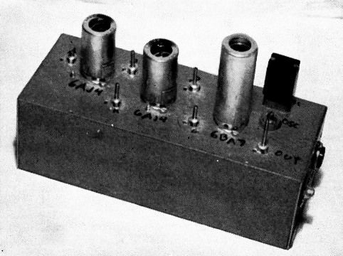
The low cross-talk converter for 50 Mc. is built in a 4 × 8 × 2 inch box.
Six-meter converters have been designed for greatest sensitivity with little thought about other defects. Grid-leak bias mixers are the rule since these work very well on weak signals and only require a volt or less of injection from the oscillator for maximum sensitivity in their mixer action. By the same token, a strong signal or two in the band can cause mixing action, and thus cross modulation, on the desired signal. This is fed into the i.f. system and no degree of selectivity there will be of any help. The answer is to use a more linear type of mixer such as a low- or medium-mu triode, with cathode bias instead of grid-leak bias, or to use a screen-grid mixer tube such as a 6BA7. The noise figure of this pentagrid mixer is lower than that of older types such as a 65A7, so it should be better for operation at 50 Mc. The 6BA7 noise figure is higher than for triode mixer, but its freedom from cross-modulation effects is better, even when enough radio-frequency amplification is used ahead of it to arrive at a low over-all noise figure.
The six-meter converter illustrated here was built to test some of these ideas. It consists of two 6AJ4 grounded-grid r.f. stages and a 6BA7 oscillator- mixer. The grounded-grid r.f. amplifier is fairly free of cross-talk and has a very low noise figure. It also is exceptionally stable and free of regenerative effects. The gain per stage is not over 3 or 4, thus permitting the use of two stages ahead of the 6BA7. This allows use of band-pass tuning to cover 50 to 54 Mc., and the extra tuned circuits help to eliminate image responses. The image rejection was measured at 80 dB. The spurious signal response to any frequency was measured at values of 60 to 80 db. down from the desired signal. This is a great improvement over the usual 10 to 30 dB.
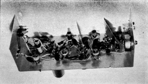
Interior of the W6AJF 50 Mc. converter. The grounded-grid r.f. amplifier stages have small isolation shields across their sockets.
The noise figure runs between 2 and 3 dB over the band, which is more than ample for weak-signal reception in the quietest location. This low noise figure also makes the converter a good first i.f. system for the 432 or 220 Mc. bands, or even 144 Mc. A signal of 0.25 microvolt will produce a good usable response in a reasonably selective communication receiver.
The i.f. tunes from 30 to 34 Mc. A lower i.f. range can be used if a higher-frequency crystal is used in the 6BA7 oscillator circuit. The oscillator coil should tune through the desired injection frequency, and the 6BA7 plate circuit should be broadly resonant at the i.f. output frequency. The latter calls for high L/C ratio and tight link coupling on the output coil.
Band-pass circuits between stages permit higher-Q tuned circuits, resulting in better image rejection and more uniform response across the band than would be possible with capacitive coupling. All of the 50-Mc. coils were wound with 10 turns on an iron-slug coil form, 5/16 inch diameter, to cover 3/8 inch winding length. Nine turns may be used with 3/8 inch CTC iron-slug tuned forms. Two-turn links on each interstage coil provide a good band-pass effect.
The cathode of each grounded-grid stage taps into the coil at about 3 turns up from the grounded end. This provides about the best "mismatch" for optimum noise figure, with only a moderate reduction in over-all gain. The cathode input resistance is a little over 100 ohms for a 6AJ4 tube, so a good noise figure can be obtained when it looks into a 200 to 300 ohm input impedance. The usual 50-ohm coax input circuit should tap into the input coil approximately half as far up as the cathode tap, or at 1 turns.
The first grounded-grid stage is protected from damage from the station transmitter by means of a grid leak 50,000 to 100,000 ohms, to limit grid current during transmission periods. The grid is grounded for r.f. by means of .002 µF ceramic capacitors, with very short leads to chassis ground lugs. Some r.f. leakage across an antenna relay can convert a fine new grounded-grid amplifier tube into a noise generator with no amplification, unless this precaution is taken, or the cathode d.c. circuit is broken by auxiliary contacts on the relay.
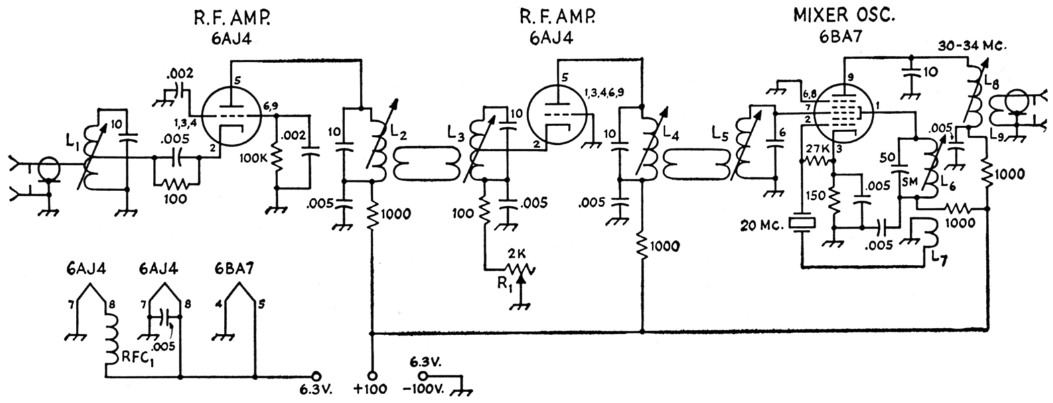
Fig. 1. Schematic diagram and parts information for the 50-Mc. converter.
Capacitor values below .001 are in pF. Resistors are ½ watt. SM indicates silver-mica.
| L1-L5 inc. | 10 turns No. 22 enam., 3/8 inch long, on 5/16 inch iron-slug coil form. Cathode taps at 3 turns; antenna tap at 1½ turns. Link windings each 2 turns. |
| L6 | 12 turns No. 22 enam., 3/8 inch long, on 3/8 inch brass-slug form. |
| L7 | 1 turn insulated hookup wire; see text. |
| L8 | 17 turns No. 22 enam., close-wound, on 5/16-inch iron-slug form. |
| L9 | 3 turns insulated wire around cold end of L8. |
| R1 | 2000 ohm potentiometer. |
| RFC1 | 20 turns No. 26 enam. 1/8 inch diam. close-wound. Slip inside spaghetti tubing. |
The second r.f. stage has a gain control in the cathode circuit. This is used only in case of operation near another six-meter station with a signal strong enough to overload the 6BA7 tube. Normally, this 2000-ohm variable resistor is left set at zero resistance, for maximum gain in the second stage.
The overtone crystal oscillator uses a tuned "plate" circuit with the screen grid of the 6BA7 acting as the oscillator plate. With some overtone crystals extra feedback is needed. This is shown in the form of a single turn of hook-up wire wrapped around the tuned circuit in the correct winding direction, and connected in series with the crystal to ground. The correct winding direction is such that the two coils are, in effect, a continuous winding from plate to the crystal. The oscillator screen voltage resistor can be set to give about 10 volts of r.f. on grid pin 2 of the 6BA7, or about ½ mA d.c. through the grid leak. Some experimenting with the cathode and screen grid resistors is advisable with a given overtone crystal, in order to arrive at good sensitivity and minimum cross-modulation effects.
The r.f. circuits can be set individually to about 52 Mc. with a grid-dip oscillator, shorting out the other coils not being adjusted. The tubes should be in place, but no power should be applied to the converter. Then a crystal noise generator can be used to tune up all the circuits for minimum noise figure at several places in the 50-Mc. band, with the converter in operation connected to a communication receiver. With a few minutes' work on this nearly uniform sensitivity and low over-all noise figure can be obtained.
Frank C. Jones, W6AJF.