A 200 Watt balun coupler for center-fed antennas
Feeding balanced line from Pi network.
In feeding a balanced antenna system, such as a half-wave dipole, from a pi-network output circuit, proper operation requires the use of some device for producing a balanced connection to the line from the unbalanced output of the pi section. This can be done with a link-coupled antenna tuner but the tuner requires adjustment. The balun coupler described here eliminates the need for tuning on any band. It can be switched to feed any one of three or more antennas of either dipole or folded-dipole type.
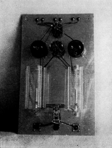
Rear view of coupler panel which serves as mounting plate for all components. Panel is aluminum, preferably at least s inch thick.
The center-fed dipole antenna remains popular even in this "beam age" because it is simple and effective. Its driving-point impedance of approximately 75 ohms unfolded and 300 ohms folded make it a natural for feeding with 75 or 300 ohm Twin-Lead, or 300 ohm Ladder Line. It can be either horizontal or vertical with numerous possible supporting arrangements. Its main disadvantage is that it is good for one band only, and an easy way out of this limitation is to use more than one.
A second problem arises because the center-fed antenna system is balanced and the output circuit of most modern multiband transmitters is a single-ended pi network. How to get power from a coaxial line into a balanced line? Antenna couplers are one answer; balun coils offer another one - a preferable one if you want to eliminate additional tuning controls.
Characteristics
Balun-coil theory is outlined briefly in recent editions of the Handbook. The balun coil consists of two separate coils wound on the same axis, with the wires of each coil spaced to give a characteristic impedance Zo equal to twice the low impedance and half the high impedance to be matched. It might be described as a two-wire line wound into a coil and it retains the characteristics of the two-wire line even though lumped in a coil.
For parallel line currents, it acts as a choke, isolating one end from a ground connection at the other end. It is effective over a wide frequency range extending from the lowest frequency for which it is designed upward.
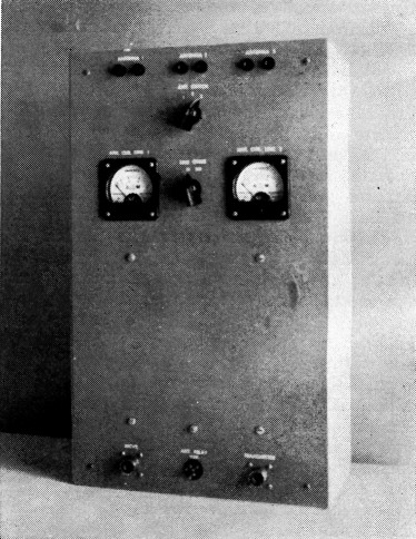
Front view of coupler mounted in a 16¼ × 10 × 4 inch box. The box is made of 3/8 inch plywood and is mounted on a window sill directly below the entry point of the three balanced lines from antennas.
The balun coils now available are designed to couple between a balanced and unbalanced line over a range of 3.5 to 30 Mc. with a single set of coils. Antennas can be switched at the balanced-line end, and no tuning adjustments are required. The coil connections are shown in Fig. 1. Each coil can be thought of as a line with a characteristic impedance of 150 ohms. Connecting the lines in parallel at both ends matches 75 ohms unbalanced to 75 ohms balanced. Connecting the lines in series at the balanced end matches 75 ohms unbalanced to 300 ohms balanced.
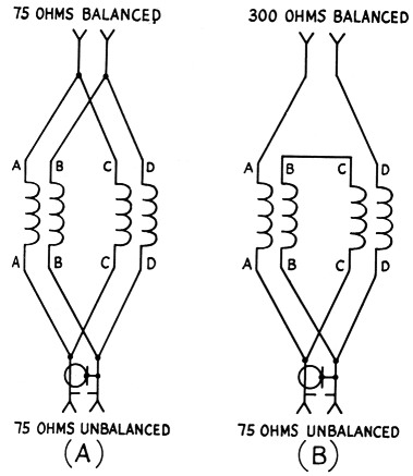
Fig. 1. Basic circuits for connecting balun coils.
(A) Both ends connected in parallel for matching 75 ohm coax to 75 ohm Twin-Lead line,
(B) Balanced end connected in series for matching 75 ohm coax to 300 ohm Twin-Lead or Ladder Line.
Construction
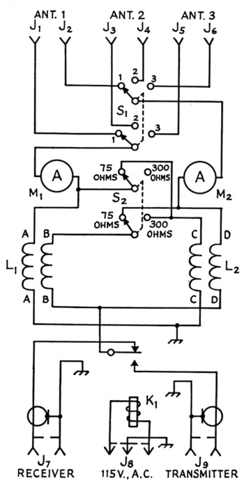
Fig. 2. Circuit of the balun coupler.
Figs. 2 and 3 describe a balun-coupler unit designed to perform three functions: (1) select one of three antennas, (2) connect it to the balun coils in either 1-to-1 or 4-to-1 impedance ratio, and (3) relay-switch the unbalanced end of the baluns to coax lines going to receiver and transmitter. Although in this unit it was desired to switch only three antennas, there is space on the panel for two more sets of antenna jacks if five-band coverage is wanted.
| J1-J6, inc. | Insulated banana jack. |
| J7,J9 | Coax receptacle (S0-239). |
| J8 | Three-pin miniature male connector (Amphenol 86-CP-3S). |
| K1 | S.p.d.t. relay, 115-volt coil (Advance AM/2C-1 pole used). |
| L1,L2 | Balun coil unit (Air Dux B2009). |
| M1,M2 | 2 inch r.f. ammeter; 3 A for 75 ohm, 1.5 A for 300 ohm line at 200 watts r.f. output. |
| S1 | Antenna-selector switch: bakelite rotary, 2 wafers, 1 pole per wafer, 3 positions (Centralab 1411). |
| S2 | Series-parallel switch: bakelite rotary, 2 wafers, 1 pole per wafer, 2 positions (Centralab 1411). |
As shown in Fig. 3, the arrangement of components and wiring is made so as to keep symmetry between the two halves of the line circuit from the point where the leads leave the selector switch, through the meters down to the balun terminals, so as to preserve balance in the system. It is desirable that the baluns be mounted on a metal plate at least 8 inches square although the coils need not be completely enclosed by metal shielding. The aluminum mounting plate also serves as the front panel.
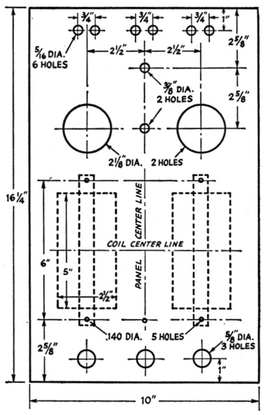
Fig. 3. Panel layout of holes, showing dimensions of balun coils. Coil centers should be at least 4.4 inches apart.
Since it was desired to use the same antenna for both transmitting and receiving, the unbalanced end of the system is switched to two coax receptacles through a small relay. The relay shown is adequate for powers up to 200 watts and frequencies up to 30 megacycles. For higher frequencies or higher power, a coaxial-type relay would be preferable. A shielded 115 volt line terminating in a 3-pin miniature receptacle powers the relay and connects the shield to the panel through the male connector, J8.
Balance
Meter readings during transmitting give an indication of whether the balanced end of the system is truly balanced, in which case the two meters read identically. With either horizontal or vertical dipoles having the line running a reasonable distance perpendicular from the center, the unit was found to give excellent balance. A check of the amount of unbalance which might be expected when coupling a Twin-Lead line directly to a pi-network transmitter output was made by connecting the leads from the meters to the transmitter coax receptacle, bypassing the baluns. The unbalance under this condition as indicated by difference in meter readings was 10 per cent. The meters were included in this unit primarily to verify and check balance, and they could be omitted with the assurance that the line currents will be equal if the antenna itself meets the conditions of balance mentioned above.
Aside from the assurance of having good balance and minimum radiation from the feed line when using the balun coupler, a major operating advantage is that no antenna tuning adjustments are necessary when changing bands.
How does it work? This question will probably be on your mind before deciding to invest in a set of balun coils.
The other night, W6QPM, a few houses down the street, pushing 800 watts into a 3 element 14 Mc. beam 50 feet high, worked UA1OE and got a 559 report. A short while later, W6EBY, nursing 150 watts through the balun coupler into a vertical dipole, worked him and got the same report! Let us disregard the statistics on our relative ratios of worked/called and other such comparative data, and close the subject by saying that it can happen!
Acknowledgment is made to Mac Petersen, W6BIQ, and Les Worcester of Illumitronic Engineering Co. for their assistance.
J.M. Shulman, W6EBY.