A "wonder" on 20 meters
Loaded dipole with fanned conductors.
Impressed with the compactness and simplicity of the 10-meter "Wonder-Bar" antenna described by K6OFM in an earlier issue, W5ECP has extended the principle to the 20-meter band with convincing results.
It was in the wee hours of a cold December night that an excited call from W5KF aroused my interest. "Say, Ralph, what would be the results if we cut K6OFM's 'Wonder-Bar'(1) for twenty meters?"
Thus one Saturday afternoon the antenna was raised. So well did the "Wonder-Bar" perform with 12 watts input that this article was written.
The "Wonder-Bar" is a simple center-loaded dipole with fanned conductors. Two advantages are noted. The first is that the fanning of the conductors produces a broad band width; the second is that the antenna, as used by K6OFM, is one half the length of a standard dipole. A week end and only fifteen dollars will make the antenna, complete with coax and mast.
Construction
For each bow, two 8 foot lengths of ¾ inch lightweight aluminum tubing were used as radials. Electrical conduit or thin-wall steel tubing may be substituted. It was felt that tubing smaller than % inch in diameter would bend near the tie bar under wind stresses. The larger-diameter tubing should also improve the antenna bandwidth characteristics.
After the tubing or conduit is cut to 8 foot lengths, one end of each piece is flattened in a vise for a length of 2 inches. One half inch from the opposite end a hole is drilled for an 8-32 machine screw. A heavy solder lug is then bolted to the rod through the hole.
A varnished board, ½ by 8 by 15 inches, is used as the center support. Two radials, which make up one bow, are placed on the board so that the flattened ends of the radials overlap each other. The place of overlapping is located on the midline of the board 5 inches from the end. The free ends of the radials are spread so that the ends are five feet apart. Holes for U clamps are drilled close to the end of the board.
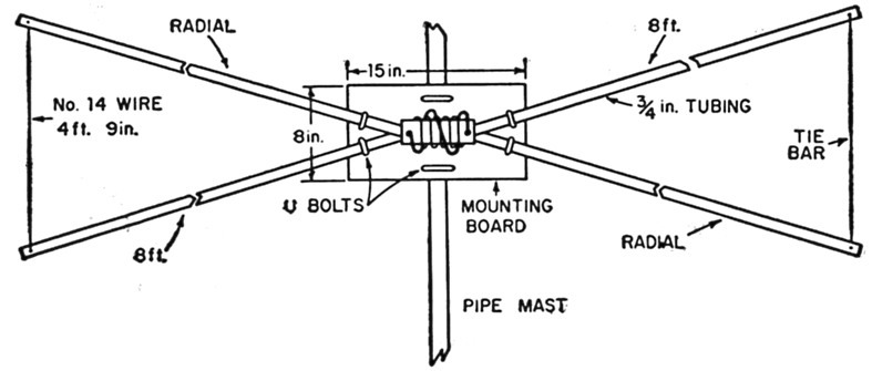
Fig. 1. Sketch showing the dimensions of the "wonder-bar" antenna for 20 meters.
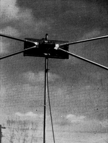
The radials of the 20-meter "wonder-bar" arc clamped to the mounting board by means of U bolts. The loading coil and coupling link are at the center.
A hole is drilled through the center of the two overlapping ends and continued through the board. A 3½-inch bolt is passed through the wood first, and then through the rods, clamping the end of the bow securely to the board. A lock washer is used under the nut, and a large flat washer under the bolt head, next to the wooden surface. Tighten the bolt firmly to assure good electrical contact between the two radials. The remaining length of the bolt is left so that a coil form can be mounted. The same method is used for the construction of the other bow. If high power is used, it is suggested that six stand-off insulators be used in place of the four U bolts and two long bolts.
To economize, No. 14 wire, 4 feet 9 inches long, is soldered between the already-mounted solder lugs. Tension produced by the lack of 3 inches of No. 14 wire adds rigidity.
Loading coil
A 5 inch spacing between bows was left for the coil mounting. Thirty turns of No. 12 plastic-covered wire are close-wound on a 1¼ inch diameter Lucite form, 6 inches in length. A hole is drilled at each end of the winding, and a 1 inch stand-off insulator is bolted to the form at each end. The coupling coil consists of 5 turns of No. 12 wire wound on a 2-inch diameter and centered over the loading coil. This coil is fastened to the stand-offs, along with the 52 ohm coaxial feed line (RG-8/U or RG-58/U). The ends of the form are drilled so that the extensions of the bolts which clamp the intersection of the radials will pass through the ends. The Lucite form, together with the ends of the 30-turn coil, are then fastened in place with an additional pair of nuts. The resulting antenna cost four dollars!
Any convenient technique may be used for mounting the antenna. If a pipe is used as a mast, the board may be simply clamped to the pipe with U bolts. You can give the antenna a paint or lacquer finish.
Only 13½ turns were needed to resonate the experimental antenna at 14.15 Mc. The other 17 turns are shorted. Fewer turns could probably be used on the main winding, say 15 to 20, and still allow ample latitude for adjustment. S.w.r. measurements show that the number of turns is quite critical, so trial and error will have to determine the position of the tap on the coil. The antenna was raised 25 feet off the ground.
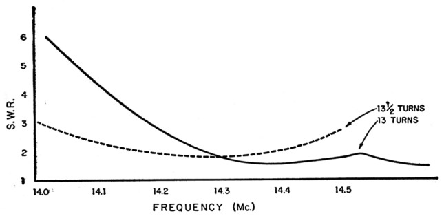
Fig. 2. S.w.r. measurements showing the importance of adjusting the number of turns in the loading coil.
Performance
The antenna has performed excellently both on c.w. and phone. Because of its lightness, good performance, size, and ability to be rotated and quickly disassembled, the antenna should be excellent for Field Day and contest work.
The "wonder-bar" is bidirectional, and to work a desired area, the radials should be broadside to that direction. If a rotator is used, it is necessary to rotate the antenna only 180 degrees.
It was found that with 30 turns in the loading coil, the antenna resonated at 9 Mc. With additional turns, the antenna might be put on 40 meters. It is also suggested that a beam could be made out of two "Wonder-Bars" for 20 meters.
Notes
Ralph Rosenbaum, W5ECP.