Test meters and how to use them
Some basic principles of trouble shooting.
A test meter is a mighty useful gadget to have around the shack when a piece of gear, for no obvious reason, isn't working properly. In this article WJICP discusses the advantages and disadvantages of some of the various test meters and then goes on to show how they are used.
Sooner or later in amateur radio the ham is R going to have to learn how to trouble shoot. By trouble shooting we mean finding what is wrong with a piece of equipment and fixing it. Whether one builds a kit or a homebrew piece of equipment - or even has a store-bought rig - the day is likely to come when something goes wrong and the unit needs fixing. In this article we propose to show you a simple method of pinpointing trouble sources.
Equipment needed
An important piece of test equipment needed by the ham who wants to do his own servicing is a volt-ohm-milliammeter (v.o.m.). This is a single instrument that is capable of measuring resistances, direct current, and a.c. or d.c. volttages. Such a meter is a sound investment for the ham because he will find it has many uses in the shack. However, before running out to the store and buying the first unit you see, write some or all of the distributors of ham equipment listed in QST and obtain their latest catalogues and sales flyers. Then you'll be in a position to get the best buy for your money.
When you start looking through the catalogues you'll find that the test meters are rated by "ohms-per-volt." The number of ohms-per-volt determines the sensitivity of the instrument. For example, when the 250-volt scale of a 1000 ohms per volt meter is used, the meter has a total resistance of 1000 times 250 or 250,000 ohms. By Ohm's Law, the current required for full-scale deflection would be 1 ma., which means the instrument uses a 0-1 mA meter. Another common type of test meter is the 20,000 ohms per volt unit which uses a 50-microampere meter. Also, you'll see advertisements for vacuum-tube voltmeters (v.t.v.m.) both as kits and completed units. Their advantage lies in their very high resistance (10 megohms or more).
Advantages and disadvantages
Each of the three instruments listed above has certain limitations. The accuracy of any voltage reading will depend on the calibration accuracy of the meter and to what extent the meter "loads" the circuit being tested. A 1000 ohmsper-volt unit uses less resistance in series with the meter than the other two types, and consequently more current will be drawn from a circuit being checked. However, once you understand this point, you can use the 1000 ohm per volt meter for most transmitter work. The only place in a transmitter where this type of meter may he at a disadvantage is in checking the grid bias across a high-resistance grid leak. If the meter resistance is less than 8 or 10 times the grid-leak resistance, it is better to use the meter as a milliammeter and connect it between the grid resistor and ground.
If receiver or high-resistance circuit trouble shooting is contemplated, then purchase either a 20,000 ohm per volt v.o.m. or a v.t.v.m.
The v.t.v.m. will measure a.c. and d.c. voltages and also resistance. Most commercial units have an input resistance of 11 megohms and consequently any loading of a circuit being tested is held to a minimum. The v.t.v.m. does not measure current but it is a simple matter to determine the current flow by checking the voltage drop across a known resistor and then using Ohm's Law.
The v.t.v.m. requires a 115 volt a.c. power source as it does not use batteries for its power supply. Unless the v.t.v.m. is well shielded and the line cord is filtered, it is susceptible to r.f. pickup when working around an operating transmitter.
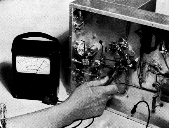
It is convenient to clip the leads to the circuits under test.
Using the test meter
There are a couple of important points to remember when using your test meter. Never, never, use ohmmeter scales to check live circuits. If there are voltages present in a piece of equipment being checked don't use the ohmmeter scales.
Always use the highest voltage or current scale when checking an unknown quantity. Otherwise you may have a burned out piece of test equipment or a badly bent meter pointer.
The test meters are usually furnished with insulated leads that have metal probes at the tips. The tips are OK for some tests but you'll find many instances when it is more convenient to clip the leads to the circuit being tested. There are insulated clips available that will slip over the ends of the probes and at least one should be purchased for your test meter.
Safety first
In doing trouble shooting the most important thing to remember is that you are working with dangerous voltages and currents. You cannot permit yourself to be careless at any time you are testing a live circuit. Turning the power off is not always a sure method of removing voltages from a piece of gear. If the bleeder resistor should happen to open up, the capacitors in the power supply may retain their charges for long periods of time. To be safe, take a metal screwdriver that has a well-insulated handle and short the hot power supply lead to the chassis. This will discharge the capacitors. Many amateurs are inclined to be careless around low voltages, believing that only high voltages are dangerous. Whenever you do any trouble shooting always remember that you are working with live circuits - get careless and the circuits may be live but you won't!
Where to start
Fig. 1 is a circuit diagram typical of a rig used by many amateurs. It consists of a crystal oscillator and an amplifier. We'll use this circuit to illustrate the various check points in trouble shooting.
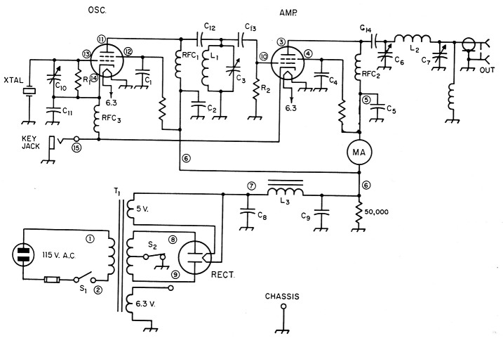
Fig. 1. Circuit diagram of two-tube typical transmitter with power supply.
When something goes wrong in a piece of equipment that has been operating there are a few things the operator should check before doing any voltage testing. Such obvious things as key leads, a.c. power source and plug, fuse, antenna system, etc., should all be checked out. If the tubes are glass, look and see if the heaters are lighting. If the tubes are metal, see if the envelopes are warm to the touch. Should one be hot and the other cold, try another tube in place of the cold one. In other words, try to analyze the problem before actually digging into the equipment.
When a piece of gear fails there are three signposts that will narrow our trouble-shooting area. First, the tubes don't light or aren't warm. Second, there is no plate current present. And last, no grid current shows. In Fig. 1 we don't show meter switching but most transmitters meter both the grid and plate by switching.
We'll start our trouble shooting by taking each of the three visible signs and going through them separately. Table 1 shows the expected meter readings, check points, and trouble spots for the heater circuits, excluding the obvious checking of the a.c. line power, switch Si and fuse to the power transformer, T1. The v.o.m. scale used for each check will depend on the voltage being checked. However, always remember to use the highest scale when checking an unknown voltage point.
| Heaters don't light or tubes are cold to the touch. | ||
|---|---|---|
| Check points | Normal reading | If no reading, possible cause |
| With S1 closed, between 1 and 2 | 115 volts a.c. | Faulty power switch. Blown fuse. Faulty wiring in line cord or plug. Blown fuse in house wiring. |
| Across 6.3 volt heater winding on power transformer. | 6.3 volts a.c. | Open heater winding.1 |
| Between the heater pins at tube sockets. | 6.3 volts a.c. | Poor ground connection for 6.3 volt winding. Bad connections at tube sockets or terminal soldering pointa on heater line. Poor ground connections at socket. |
| Heater pins on tubes. Remove tubes from sockets for this check. | Low resistance.2 | Open heater. |
| 1 An open heater winding doesn't mean a new power transformer is required. A filament transformer can be installed in the transmitter and the power transformer can be retained. 2 Always use the low resistance scales of the test meter for continuity checks, unless it is desired to check the resistance in a circuit or continuity through high-resistance circuits. | ||
You will notice reference to bad wiring and this can mean faulty soldering, poor connections, etc. When checking at a terminal point that has several branches, the test probe should be touched to each of the component leads, not just the terminal point. Also, a common wiring error beginners make is to solder insulated wire ends to terminals - particularly enameled covered wire. Always remove the insulation and clean the ends of the wires before soldering.
In table 1, the first column gives the check points where the v.o.m. leads are connected. The second column shows the expected meter reading. The last column lists expected trouble spots.
No plate current
In our checking in table 1 we had a clear-cut road to follow. However, in finding why there is no plate current our road has several branches which must be checked out. In table 2 each check point will show us what is happening up to that particular point. Before doing any checking with the test meter there are a few things to look for that may be the cause of trouble. First, be sure that the key leads haven't been disconnected. If the key isn't closing the circuit then the cathodes of the oscillator and amplifier are not being connected to chassis ground and the tubes won't draw current. If there is grid current but not plate current, then it can be assumed that the power supply is working. However, due to a faulty component or wiring, the power supply output may not be reaching the amplifier. Should you have output from the rig and show no plate current, then it is apparent that the meter isn't functioning or the movement is sticking.
| R.F. Tubes lit but no plate current indicated | |||
|---|---|---|---|
| Measure + voltage between chassis and check point: | Voltage | Cause | |
| Yes | No | ||
| 3 | X | See note at bottom of chart. | |
| 3 | X | This indicates power supplyvoltage is OK but there is an open circuit between points 6 and 3. | |
| 6 | X | ||
| 3 | X | Meter OK, but RFC2 is open. | |
| 5 | X | ||
| 5 | X | Meter open. | |
| 6 | X | ||
| 4 | X | Open screen dropping resistor, or C4 shorted. | |
| 5 | X | ||
| 7 | X | Open filament in rectifiertube, wiring error or faulty transformer winding. | |
| 8 or 9; close S1. | X | Bad rectifier tube. Bad connections at rectifier socket. | |
| (Use 1000 V a.c. scale) | X | Faulty switch at S2. Open winding in high voltage secondary of T1. | |
| If there is voltage at the plate and screen of the amplifier and the circuit being tested uses grid-leak bias (Fig. 1), then the probable reason for no plate current indication would be an open cathode circuit or a defective plate milliammeter. | |||
With the heater checks we were only concerned with a.c. so voltage polarity was no problem. In table 2 we will be working with d.c. and the chassis ground is our reference point; the volta ges are either positive or negative with respect to chassis. On the test meter, the lead jacks are marked plus and minus or are red and black. The black is minus or negative, and this lead is connected to chassis ground for all of the checks in Table 2. Our positive lead is the one used for all the checks.
If there is plate voltage present and the tube does not draw current, there are three things to look for. An open cathode circuit will prevent current from flowing. If there is no voltage at the screen grid, very little or no current will flow. And last, if the grid is biased beyond cut off (and there is no grid drive), the tube won't conduct.
In table 2 we start off at the plate of the tube and work back to the power supply. The first column gives the check point, which is the circled number in Fig. 1. The next two columns indicate the presence of voltage. There are no definite values for voltages given because they would probably be meaningless if applied to your rig. Your instruction manual will give the important voltage and current values and these can be applied in your testing. The last column gives the cause of the trouble.
No grid current
Before making voltage measurements for grid current there are some simple checks that can be tried which may show the trouble spot. Listen to your receiver at the crystal frequency for the oscillator signal. If there is no signal then try another crystal, and don't forget to tune the receiver to the new crystal frequency. Should there be a signal heard from the oscillator, then tune C3 to see if the amplitude of the signal changes. If it does - and gets louder at one point of the tuning - it indicates the oscillator and tuned circuit are operating properly. The trouble is then likely to be in the meter failing to read and show grid current. On any of the tests mentioned above, don't hold the key down any longer than necessary, as the amplifier tube will draw excessive plate current when no excitation is reaching it.
In table 3 all voltage measurements are made in the same manner as in table 2, with the exception of the check at point 10. This is the grid of the amplifier and the voltage will be negative with respect to chassis. The meter leads should be reversed for this test, positive lead to chassis ground and the negative lead for testing. Also, a 2.5 mH r.f. choke must be connected in series with the test lead when checking at point 10. Otherwise, the test meter will detune the grid circuit and no reading or an incorrect one will result. If your transmitter has an r.f. choke between grid and grid leak (R2), then you won't need to use another r.f. choke; the test probe can be touched to the junction of the r.f. choke and the grid leak for the voltage check. If your test meter is the 1000 ohms-per-volt type, then use the highest voltage scale for this test.
| No grid current indicated. | |
|---|---|
| Step 1. | Check for voltage at point 11. If there is none, then check at point 6 to see if the power supply output is present. If the supply is not functioning, refer to Table II for trouble shooting. Voltage at point 6 and none at 11 indicates bad wiring or open RFC). |
| Step 2. | Voltage at point 6 and none at point 12 indicates bad wiring, open screen dropping resistor or shorted Ci. Check resistor with ohmmeter. Check Ci by removing oscillator tube and measuring resistance between point 12 and ground. |
| Step 3. | Turn off power and switch test meter to read ohms (high resistance). |
| Step 4. | Leave one test lead at point 14 and move other lead to point 15. Meter should show continuity. If not, it indicates bad wiring or open RFC,. |
| Step 5. | Move lead at point 15 to the grounded terminal of key jack and leave attached at point 14. Open and close key. The meter should read when key is closed, indicating continuity from oscillator cathode to chassis ground. If not, check wiring to key. |
| Step 6. | Turn on power, switch meter to read d.c. high voltage, connect positive meter lead to chassis and make voltage check at point 10, amplifier, with key closed. Failure to obtain reading when C3 is resonated (see text) indicates bad wiring, grid-to-cathode short or faulty components at C12, LiCe, C13, or R2. Depending on the type of test meter used, an r.f. choke may be needed in series with the test probe. (See text). |
The highest scale puts the most resistance in the voltmeter circuit, and the shunting effect on the grid leak is minimized. If a v.t.v.m. is used for testing, then it usually isn't necessary to use an r.f. choke with the probe.
Additional tests
If grid and plate current are obtained and the transmitter doesn't work, then the trouble should be in the amplifier tank circuit. Continuity checks should be made to determine if there are any wiring mistakes or bad connections. In the case of a pi network as in Fig. 1, the output capacitor C7 should be set at maximum capacity and Co tuned for resonance as indicated by the dip in plate current. If the tank circuit resonates, then you can be reasonably sure that the transmitter is working and your problem is one of loading or shorted C7.
If the transmitter is a kit or homebrew job, the most common trouble encountered is short circuits. This can be due to bits of solder or wire getting into spots they shouldn't be in, and it sometimes takes considerable searching to find them. It is a good idea to make a few resistance checks before applying power to a newly built piece of gear. The power supply B + line is usually above chassis ground by the value of the bleeder resistor. A quick check is to switch your test meter to the high resistance scale and connect one lead to the B + line and the other to chassis ground. The ohmmeter will quickly show the presence of any shorts.
Once you have the piece of equipment working it is an excellent idea to make a record of voltage readings at different test points. Suitable points would be:
- Output of power supply.
- Plate voltage of amplifier and oscillator stages.
- Screen voltage of amplifier and oscillator stages.
- Grid voltage.
These checks should be made with the transmitter operating into a load. The next time the rig acts up you'll have a record to refer to which will probably make your job easier.
It would be impossible to completely cover the subject of trouble shooting in the space permitted here. Such things as self-oscillation, parasitics, etc., are treated in The Radio Amateur's Handbook.
Lewis G. McCoy, W1ICP.