A saw-tooth crystal calibrator
Harmonic generator and amplifier with 100 kc. markers to 50 Mc.
An improved harmonic-generating circuit is used in this crystal calibrator to give more uniform output at 100 kc. intervals throughout the high-frequency spectrum. Usable marker signals can he obtained through the 50 Mc. band.
One of the nuisances connected with using conventional crystal calibrators is the drop in marker strength at the higher frequencies. At 10 meters, when the band is open, it is sometimes impossible to hear the markers through interference and background noise. The 100 kc. crystal calibrator described here uses a conventional type oscillator, but its output is fed into a network that converts it into a saw-tooth wave,(1) a wave form which is superior to others in this application because of its more uniform harmonic content. Incorporating a tuned amplifier, the device provides entirely adequate output up to 30 Mc. and usable harmonics to 50 Mc.
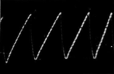
Output of the saw-tooth generator as measured at the grid of the amplifier. A wide-band (10 Mc.) oscilloscope was used to obtain this photo.
The calibrator circuit
The circuit of the calibrator is shown in Fig. 1. The triode section of a 6AN8 ( V1A) is used as a 100-kc. crystal-controlled oscillator. The output of the oscillator is fed to the saw-tooth generator network consisting of CR1, CR2, R1, C2 and C3. The operation of this circuit is as follows:
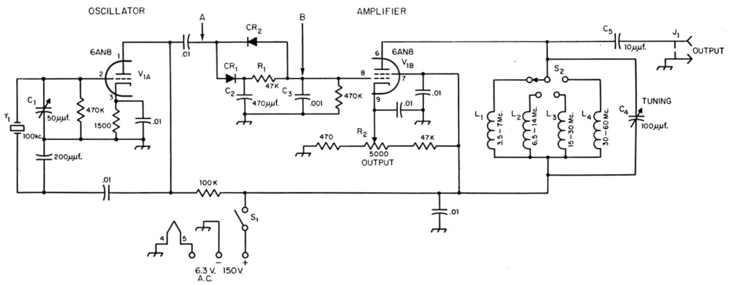
Fig. 1. Circuit of the 100 kc. crystal calibrator. Unless otherwise indicated, capacitances are in µF, resistances are in ohms, resistors are ½ watt.
| C1 | 50 pF midget variable (Hammarlund MAPC-50). |
| C4 | 100 pF variable (Hammarlund 11F-100). |
| CR1,CR2 | 1N34A. |
| J1 | Phono jack. |
| L1 | 3.5-7 Mc., 10 µH (National R-33 r.f. choke). |
| L2 | 6.5-14 Mc., 4.7 µH (IRC type CL-1 r.f. choke). |
| L3 | 15-30 Mc., 1.0 µH (IRC type CL-1 r.f. choke). |
| L4 | 30-60 Mc., 0.22 µH; 4 turns No. 20 plastic-insulated wire, 3/8 inch diam. |
| R2 | 5000 ohm potentiometer (Mallory U-14). |
| S1 | S.p.s.t., mounted on R2 (Mallory US-26). |
| S2 | 1 section, 1 pole, 4 position miniature phenolic rotary switch (Centralab PA-1000). |
| Y1 | 100 kc. crystal. |
At the beginning of the positive portion of the 100 kc. signal, point A is more positive than point B, so capacitor C3 begins to charge slowly through CR1 and R1, and the slowly-rising voltage across C3 as it becomes charged shapes the sloping portion of the saw-tooth wave. When the polarity of the 100 kc. input reverses, point A becomes more negative than point B, and since under this condition the path from B to A is practically a short circuit, through CR2, C3 can discharge rapidly, thus giving the vertical portion of the saw-tooth wave.
The saw-tooth wave is applied to the grid of the pentode section of the 6AN8, V1B, and the desired amplified harmonic is selected through the tuned circuit by setting switch S2 and capacitor C4 appropriately.
No power supply is included in this circuit. Power usually can be taken from the receiver, but a small power supply capable of delivering 150 volts at 10 ma. and 6.3 volts at 0.5 amp. can be added if a larger cabinet is used.
Construction
This particular calibrator is built in a 4 × 5 × 6-inch steel cabinet (ICA 3819), having a self-contained chassis welded to the front panel. The output control, R2, and the band switch, 52, are mounted on the panel and the remaining components are placed on the chassis. The amplifier tuning control, C4, is above d.c. ground so the shaft is brought through the panel by means of an insulated extension (ICA 2110 or Allied Radio No. 60 H 355).
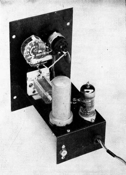
This view shows how the major compo. nents of the calibrator are mounted. The 100 kc. crystal is in the metal tube envelope. Output from the unit is taken from the phono jack at the rear of the chassis. The three leads coming through the grommet are power leads.
When mounting the tube and crystal, be sure to leave a little space between them so that heat from the tube will not cause the crystal frequency to drift. However, make the leads from the tube to the crystal as short as possible. As shown in the bottom view of the calibrator, the tube, crystal and calibrating capacitor C1 are all mounted within a short distance of each other.
Most of the wiring is associated with the tube socket and does not require any special tie points. However, for wiring convenience the saw-tooth network (components between points A and B) is soldered to a terminal strip. Leads are then run to the components on the strip.
The photograph shows how the amplifier tank inductances are soldered to the band switch, S2. With this arrangement only two leads to the tank inductance assembly are necessary.The three power leads are brought out through a grommet in the rear of the chassis for connection to the receiver or other power source.
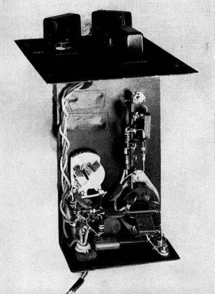
Bottom view of the calibrator. The saw-tooth network is on the terminal strip at right center. The calibrating capacitor, C1, is the small variable capacitor at the left.
Using the calibrator
The calibrator is connected to the receiver antenna post through the coupling capacitor C5. On the lower frequencies, markers from the calibrator can sometimes be detected without connecting the unit directly to the receiver, but this depends on how well the receiver is shielded. Output is fairly constant up to 30 Mc., but starts to fall off rapidly above that frequency.
To use the unit, turn on switch Si, advance the output control to full on (minimum resistance) and turn the band switch to the position covering the desired output frequency. Then tune the receiver near a check point until the signal from the calibrator is detected. The output control is used to adjust the level of signal after being peaked up by the tuning capacitor, C4.
It is advisable to check the accuracy of the 100 kc. crystal oscillator. The most common method is to zero beat a harmonic of the oscillator to one of WWV's standard frequency signals. WWV schedules and the procedure for adjusting to zero beat are given in the chapter on measurements in the Handbook. The frequency adjustment is made by tuning capacitor C1 to zero beat.
Once the 100 kc. oscillator frequency has been set the calibrator can provide accurate marker signals every 100 kc., as far up in the spectrum as 50 Mc. These markers can be used to calibrate a receiver, to set a v.f.o. for band-edge operation, or for any other general calibration purpose.
Notes
E. Laird Campbell, W1CUT.