Simple gamma-match construction
Any of us have shied away from using a gamma match because of the problem of providing a suitable waterproof container for the gamma capacitor. The following is a description of a gamma match used by the author which will overcome this difficulty and also provide a good mechanical assembly.(1) Once adjusted, it may be easily waterproofed and will not be subject to changes due to vibration. The one in use by the author has been up for over a year without any necessity for readjustment.
Referring to the accompanying drawing, the ¾ inch aluminum, the 5/8 inch polystyrene and the ½ inch aluminum tubings form the gamma capacitor. The ½ inch tubing has been extended to form the gamma rod. Varying the dimension A changes the capacitance of the gamma capacitor. This value changes at the rate of approximately 15 µµf. per inch engaged. The length of the gamma rod is controlled by dimension C. The table gives maximum dimensions for the various bands.
Adjustment
Adjustment procedure is the same as with the conventional gamma match. The author's two-element 20-meter beam was adjusted in approximately one-half hour as follows:
- The elements were adjusted to the desired frequency using the ARRL Handbook data.
- An s.w.r. bridge was connected at the station exciter and to the beam through an electrical half-wave length of 52-ohm coax.
- Measurements of s.w.r. were taken throughout the 20 meter band with the gamma capacitor and rod set at the maximum dimensions. It was found that the point of minimum s.w.r., although high, was still at the desired frequency.
- With the exciter at this frequency, the length of the gamma rod was decreased for minimum s.w.r.
- With the gamma rod clamped tight to the driven element, the capacitance of the gamma capacitor was varied to further reduce the s.w.r. This can be done by leaving the clamp tight on the driven element and sliding the gamma rod in the lower part of the clamp.
Because of the interaction between adjustments, it may be necessary to repeat steps 4 and 5 several times. With careful adjustment the s.w.r. can be brought close to 1 to 1. The writer ended up with dimension A as 6 inches and dimension C as 40 inches with a center frequency of 14.250 kc. Adjustments were made at 15 feet above ground and did not change appreciably when the antenna was raised to 35 feet. Once a match has been obtained any convenient length of feed line may be used.
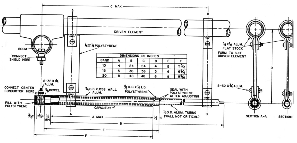
Fig. 1. Sketch showing the constructional details of the gamma matching section used at W2VS for 52-ohm coax line. The reactance-compensating capacitor is in tubular form. It is made by dividing the gamma rod or bar into two telescoping sections separated by a length of polystyrene tubing which serves as the dielectric.
Several coats of polystyrene cement or similar material at the joints and end will provide the necessary waterproofing and rigidity.
A similar setup could be used with a T match or, with suitable dimensions, on the higher frequency bands.
Notes
Fred Reymolds, W2VS.