Wavemeters using butterfly tank circuits
135 to 1000 Mc. in two handy units.
Its high circuit Q, compactness, and large tuning range make the butterfly-type tuned circuit a "natural" for use as a frequency measuring device. Its rigid construction and mechanical simplicity insure high stability and permanent calibration. The wavemeters shown here can be constructed using simple hand tools, and their accuracy is limited only by the care used in calibrating them. The butterfly units used in these wavemeters are available from many surplus houses. The tuning ranges of the two described are 135 to 485 Mc., and 300 to 1000 Mc.
How the butterfly circuit works
The butterfly is, in essence, a complete tuned circuit containing both inductance and capacitance. The ones used in this case are of the type shown in Fig. 1A. The equivalent electrical circuit is shown in Fig. 1B. The electrical circuit between points A and A' is equivalent to a high-impedance tuned circuit and external connections to the circuit are usually made at these two points. Points B and B' are the electrical midpoints of the circuit, and either one may be used. When the rotor is in the dotted position (see Fig. 1A) the capacitance and inductance of the unit are both at their maximum and the circuit is resonant at its lowest frequency.
The total circuit capacitance is composed of two parts, at A and A'. The two capacitances are in series, which reduces the total of the circuit. The inductance of the circuit consists of the two semicircular strips which are shown shaded. Notice that these are in parallel, which reduces the total circuit inductance. As the rotor is moved out into the space where it no longer meshes with the stator plates the capacitance is decreased and at the same time the inductance is decreased, as the rotor has now occupied an area which was previously filled by lines of flux encircling the inductance strips. It is this unique feature of simultaneous variation of both inductance and capacitance which gives the butterfly its large tuning range; in some units as great as eight to one. The price paid for this extended tuning range is a reduction in the angle that the rotor turns in going from the low to the high-frequency positions. This angle is approximately 85 degrees.
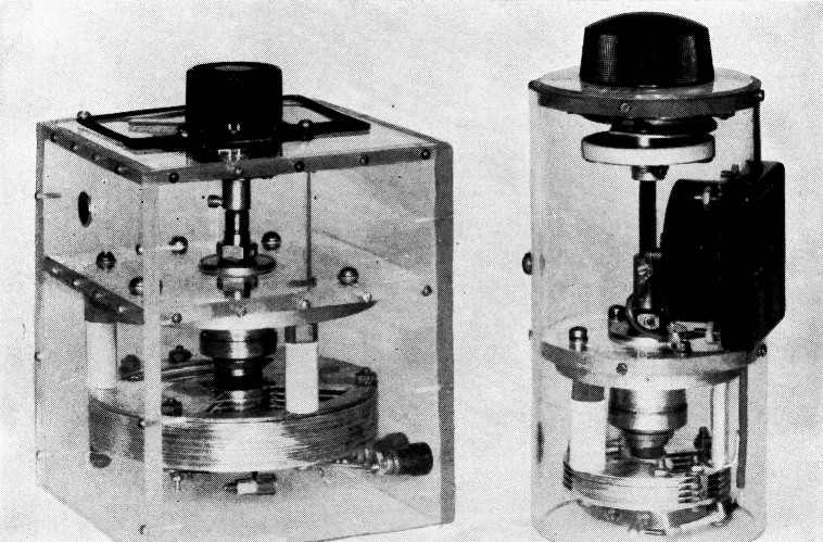
The two butterfly wavemeters. The larger covers 135 to 485 Mc. The smaller tunes 300 to 1000 Mc.
A schematic diagram for both wavemeters is shown in Fig. 1. When the circuit is resonant at the frequency being measured, a large r.f. voltage is developed across points A and A'. To preserve the Q of the circuit only half of this voltage is rectified and applied to a d.c. microammeter. Capacitor C1 provides a return path for the r.f. current, preventing it from flowing in the meter. A 1N23 crystal is recommended for the high-frequency unit, a 1N21 for the lower.
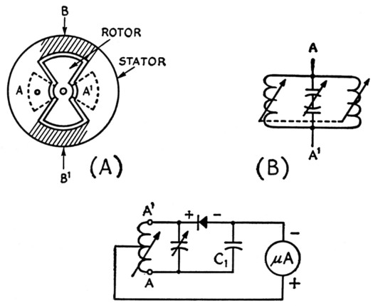
Fig. 1. The butterfly tank circuit, A, is in effect two inductors in parallel, tuned by two capacitors in series. High-impedance points are at A and A'; low-impedance points at B and B'. The equivalent circuit is shown at B. In the circuit for the wavemeter C1 is an inherent part of the small butterfly. For the larger unit it should be about 90 pF.
Construction
The high-frequency unit is housed in a 6½ inch length of ¼ inch Plexiglass tubing of 3½ inch outside diameter. Two disks of quarter-inch plastic are cut to fit snugly inside the tubing. The butterfly is mounted on one of the plastic disks and the National tuning mechanism on the other. A hole was cut in the plastic tubing to accommodate the 0-100 microampere meter.
The unit is assembled as shown in the photograph, the disks being fastened to the tubing with No. 2 self-tapping screws. A 3 inch-diameter dial is cut from 1/16 inch plastic. White paper is glued to its back, and the dial and knob mounted on the vernier mechanism. Calibration lines are scribed into the plastic dial with a needle at the time of calibration and later filled with black ink, which makes them stand out against the white paper backing. The high-frequency unit comes with a crystal detector and by-pass capacitor mounted as shown in the photograph. The meter's positive terminal is connected to an electrical midpoint and the minus terminal is connected to the by-passed side of the crystal diode which is the larger diode terminal.
The low-frequency unit is mounted in a 5 × 5 × 5½ inch plastic box with a partition 1% inches from the top end. The material is 3¾ inch Plexiglass, fastened together by drilling and tapping for 2-56 screws. A National type MCN tuning mechanism is used and terminals are provided for an external meter. This butterfly assembly came equipped with mounting hardware for an acorn tube, but this was removed. Electrical connections are exactly the same as those for the high-frequency unit and can be clearly seen in the photograph. A crystal diode holder was improvised from a fuse clip by removing one of the clips and replacing it with a solder lug of the type which has ears to grip the wire. The lug ears are bent so that they grip the small terminal of the crystal diode. The by-pass capacitor is 90 pF.
Calibration and use
Both of the units were calibrated using a u.h.f. oscillator which was available at a local university. The accuracy of the generator was 2 per cent. An alternative method would be to use a variable-frequency oscillator and Lecher wires. Ours were calibrated simply by placing the wave-meters near the unterminated output cables of the oscillator, and rotating the butterfly until maximum meter deflection is observed. For each frequency within the range of the butterflies maximum meter deflection will be observed for two positions of the rotor. Use the position such that the resonant frequency increases with a clockwise rotation of the rotor. An indication may be obtained when the wavemeter is tuned to a harmonic of the calibrating oscillator. This indication will be much smaller than the one for the fundamental frequency.
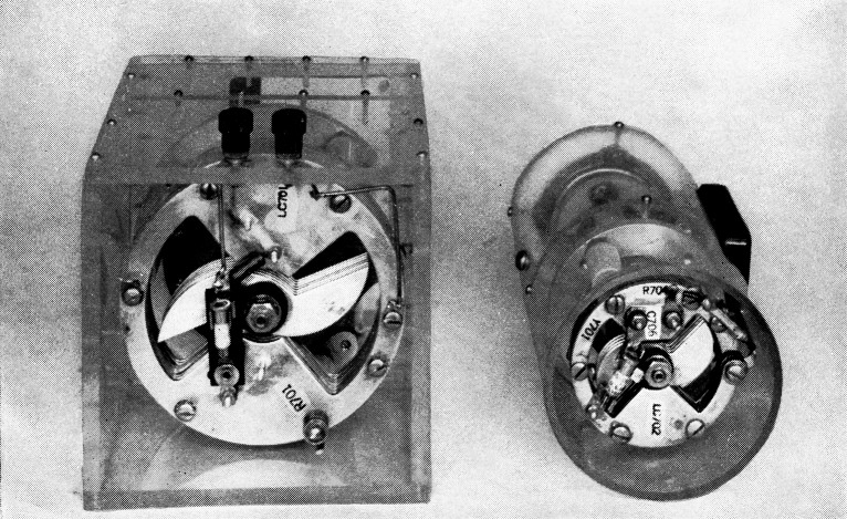
End view of the wavemeters. The crystal diode clips and by-pass capacitor are integral parts of the small unit. The crystal mount for the lower-frequency assembly is made from a fuse clip.
Operation of the completed wavemeters is extremely simple. The wavemeter is placed next to the equipment whose frequency is unknown and tuned for maximum current as indicated by the microammeter. The frequency is then read directly from the dial. The units are extremely sensitive. It was possible to obtain meter deflections with the high-frequency unit five feet away from the tuned lines of a 955 acorn tube oscillator.
One use for these wavemeters, aside from simple frequency checking, is tracking down u.h.f. parasitics. Often these are beyond the range of most absorption-type wavemeters. Being able to look for energy at frequencies above 200 Mc. or so may he very helpful in stabilizing amplifiers designed for the h.f. or v.h.f. bands.
W. Gerald Banshah.