Transistorized regenerative receiver
A compact set with good performance.
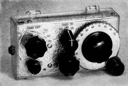
This complete transistorized ham-band receiver is built in a plastic tackle box. The bias knob at the lower left also turns on the 4%-volt battery; the lower center knob is the regeneration control.
When W6WXU, S. A. Sullivan of Sonoma, Calif., sent us the little gadget shown on these pages, we thought it was just another transistorizing stunt that could hardly be expected to show more than mediocre performance. To the great surprise - and delight - of everyone who tried the receiver, it was soon found that the set could bring in signals amazingly well on 80, 40 and 20 meters. It was all the more astonishing in view of the built-in loopstick antenna. To operate the receiver, it was only necessary to plug in a set of headphones and turn 'er on.
The circuit is shown in Fig. 1; L1 is wound on the 5_1/8 inch long rod of ½ inch diameter ferrite that also serves as the antenna. The regeneration control is a 3-30 pF compression mica trimmer, with the screw extended through the panel and terminated in a knob.
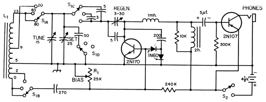
Fig. 1. Schematic diagram of the transistorized receiver. The 2N170 serves as a regenerative r.f. amplifier to feed the 1N60 detector diodes; the audio is then fed back to the base of the 2N170 and then to the 2N107, in W6WXU's transistor version of the old "reflex" circuit. The inductor L1 is wound on a ferrite rod with 23 turns of No. 24 enam., space-wound and tapped at the turns shown above. A subminiature 2 henry choke is used. Capacitances in pF unless specified otherwise.
S1 4 pole 3 position rotary.
S2 Mounted on R1.
W6WXU modestly states that the receiver was not submitted as a model for construction, although he does have a couple of good construction ideas. The "cabinet" is a small clear-plastic tackle box measuring 5% inches long, 3 inches wide and 1% inches high; the metallic look was obtained by inserting inside the box a small piece of thin ornamental aluminum sheet, the type you find at the "do-it-yourself" counter of the hardware store, cut and bent to fit. The aluminum serves as a shield against body-capacitance effects. But let the builder tell you a little about the gadget:
Of course, it is no HRO, but three bands with no antenna or ground is still pretty good for just two transistors and a pair of diodes. Admittedly, the receiver is a bit of a freak, since this particular 2N170 is the only one I have found that would hit 20 meters, out of a half dozen. I suspect that if it proves anything, it shows that manufacturers haven't got transistor production under control yet. On the other hand, all of the six transistors worked at 40 meters without any difficulty. Furthermore, even though their alpha cut-off is rated as 4 Mc., they out-perform beyond all comparison a 2N136 and a CK766 that I tried.
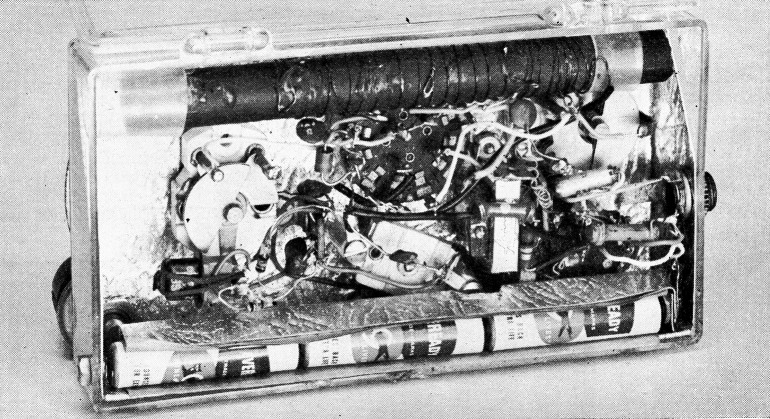
W6WXU didn't intend this to be an example of picture-book construction, but the unit works like a charm. The 3-30 pF compression trimmer (with shaft added) used for the regeneration control is at the lower center. The metal used as a shield and common ground is thin ornamental aluminum sheet.
The operation is the same as that of any regenerative receiver, with one exception. I found that the 2N170 base bias had to be set differently for each band. Otherwise the receiver tends to develop an audio howl at the edge of oscillation.
The set should be held so that the pick-up coil is at least a few inches away from other objects. It works best in a cool room and of course not at all in a shielded room.