The Norberg crud-o-ject
A simple electronic audio filter for the c.w. man.
The device described here is a means for obtaining variable audio selectivity, to he used with a receiver that is inadequate in the selectivity department. The selectivity can be varied from no peak to the point where the device breaks into oscillation.
Here is a simple device which will reduce the audio hand width of your receiver to less than 50 c.p.s. at any medium audio frequency and will noticeably improve receiver signal-to-noise ratio. It does just what its name implies: rejects the crud and saves the signal. The gadget is a simple application of a principle used in many popular selectivity-increasing devices and will give a broad communications receiver many of the advantages of a crystal filter without reducing its over-all gain. The author's model cost him just one buck, Anyone who can't duplicate it for $3.50 just doesn't have a respectable junk box.
After several months of battling QRM, QRN and ITV with his broad (but extremely stable and wonderfully inexpensive) BC-455, the author decided something had to be done. It was a matter of moving to the exciting, peaceful region above 100 Mc. or improving the receiver. The situation became indeed serious after the 1954 Sweepstakes when other hams began referring to the author as "the one with the shredded eardrums."
W0ORZ was already a familiar call on 220 and 420 Mc., but a steady A3 diet makes a true-blue c.w. man lonesome. One look at the inside of the BC-455 made it obvious that to mess up such beautifully planned wiring would be nothing short of sacrilege. The course was clear: an external audio filter.
Theory
The end result is shown schematically in Fig. 1 The basic filter circuit is a triode amplifier with a series-resonant LC circuit in the cathode lead; it will be very degenerative except at the resonant frequency.
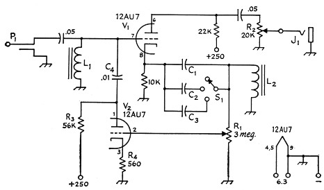
Fig. 1. Circuit diagram of the selective audio amplifier. See Fig. 2 for the circuit modification when the receiver output is low-impedance (taken from secondary of output transformer). Capacitances are in pF, resistors are watt.
| C1,C2,C3 | See text. |
| J1 | Phone jack. |
| L1,L2 | See text. |
| P1 | Phone plug. |
So far, everything is fine except that at audio frequencies high Q is hard to come by and, after all, the Q of the tuned circuit determines the sharpness of the filter. The solution to this problem is to connect a negative resistance across the tuned circuit to counteract its losses and raise its Q; feed-back amplifier V2 does just that. The voltage across L2 is 90 degrees out of phase with the filter amplifier cathode voltage at the resonant frequency. V2 amplifies part of this voltage and shifts it another 180 degrees. L1 and C4 give at least another 90 degree phase shift so that the fed-back voltage is in phase with the input signal at the one resonant frequency. R1 controls the gain of V2. making the selectivity continuously controllable. SL allows the operator to choose one of three resonant frequencies, to avoid boredom.
Design
The only designing the builder must do is in figuring out the correct constants for the tuned circuit in the cathode of V1. If the inductance of the choke L2 is known, the approximate value for C1 is given by
![]()
where
the capacitance is in µF,
the frequency in kc.
and the inductance in henrys.
Lacking a definite knowledge of the coil's inductance, one may use a small filter choke of 1 or 2 henries. The exact resonant frequency can be set to any desired value by changing the air gap between the U and I laminations. A 2-henry inductor will resonate at around 1000 cycles with about 0.01 µf. Adding capacitors C2 and C3 will lower the frequency.
L1 and C4 in series should resonate at a frequency about 1½ or 2 times higher than the resonant frequency of L2C1.
Construction details
Because most of the components used in the Crud-O-Ject will be found in the average junk box, and because the circuit layout is not at all critical, the best way to construct the gadget will be to make it as compact as the components will permit. The author's model was built on cur inverted-U 16-gauge aluminum chassis 4 inches long, 2½ inches wide and 1½ inches deep, with a 2½ × 4 inch aluminum plate serving as a panel. R1 and J1 hold the front panel on the chassis, and R2 and Si are mounted above them. The 12AU7 is mounted about in the center of the chassis.
R1 should be at least 3 megohms, in whatever taper is cheapest. The original component came from the bargain box of a local distributor and cost 10 cents. L1 and L2 can be any inductors such as audio output transformer primaries, 10 mA chokes, etc., as explained earlier. The author used a 2 henry toroid from the junk box. S1 was swiped from a surplus control box BC-450A; the whole box cost two bits at the Minneapolis Radio Club annual rummage sale.
The remaining components are not critical, although it would be a good idea to keep them within 20 per cent of the listed values.
Possible modifications
If the builder plans to use this unit with a receiver having a low impedance output transformer at the phone jack, he can eliminate L1 and the 0.05 µF capacitor. If the receiver headphone output impedance is below 2000 ohms, as many of them are, the input circuit shown in Fig. 2 should be used.
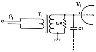
Fig. 2. If the receiver output is at low impedance, L1 and the associated 0.05 µF capacitor should be replaced by this circuit.
T1 Small tube-to-voice-coil output transformer.
If he doesn't mind listening to the same note frequency all the time, the builder can eliminate Sl completely, along with C2 and C3.
Since the Crud-O-Ject will operate between any two high-impedance audio stages and will have some gain, a stripped-down version may be inserted permanently between the first and second audio stages (or out of the phone jack) of any present or planned receiver. Merely twisting R1 to the low feed-back position effectively removes the device from the circuit for (phooey) phone reception. However, a Crud-O-Ject peaking at 1 kc. will reduce phone QRM considerably.
If R1 is advanced far enough, the device will slide into a very sinusoidal oscillation that can be used for test purposes or as a code practice tone.
Operation
As with many selectivity-increasing devices, your appreciation for the Crud-O-Ject will increase the better you learn to operate it. After no small amount of trial and error, the author discovered the following operating conditions and procedure to be most fruitful.
Plug in the input and connect the power from the receiver to the filter. After the 12A157 is warm, advance R1 until you hear the device go into oscillation. Toni dotty the receiver audio gain control to well below the point where it no longer affects the position of R1 where oscillation begins. If the circuit will not oscillate, increase R3 or bypass R4 with a 1 µF capacitor.
Then adjust R1 to the region just below oscillation. The exact point of going into oscillation should be very smooth and almost impossible to detect. If it is not, increasing R3 or R4 or changing C4 slightly should correct this. The selective region will sound like a bunch of marbles dropping into a tin can; this is random atmospheric noise "ringing" the selective circuit and is a normal result of using a very high-Q device. Since only the components of atmospheric noise that fall within the filter pass band are heard, the over-all signal-to-noise ratio is improved.
Tuning across a signal will result in a very pronounced sharp response peak where the beat note is just equal to the resonant frequency, so the operator will need to practice tuning in signals accurately. The final tuning may be done either with the main receiver dial, or with the b.f.o. pitch control. However, if your receiver is unstable, the signal will not stay on the peak.
To sum it all up, the Norberg Crud-O-Ject cannot substitute for a crystal filter, but it tries. It will make any stable receiver very sharp at very low cost. It will double as an audio oscillator and, if there are no signals in the band, you can set it into oscillation, sit back and play a tune with S1!
G.R. Norberg, W0ORZ.