Linear amplifiers and power ratings
Cool tuning of hot amplifiers.
This article points out some of the problems involved in adjusting and tuning large linear amplifiers, and it goes on to show how it can be done easily with a minimum of extra gear in the In shack. The side-band man with a small linear amplifier and large ambitions can also benefit by using the same methods.
Since the use of single side-band and EVER linear amplifiers, there has been considerable misunderstanding of the power levels involved. QST advertisements for side-band gear carry references to "p.e.p.," but there are probably many readers who interpret this as an abundance of vitamins instead of "peak envelope power."(1) Currently on the air there are instances of amateurs blithely announcing that they are "tuning up with the two-tone test and running 2 kilowatts peak input," a strictly illegal operation and a loud confession to not knowing the facts about linears and the FCC regulations. It is the intent of this article to clarify some of the points of linear-amplifier ratings and to show how a legal kilowatt linear can be tuned without breaking the law.
(What's that? Break the law with a legal kilowatt? This guy's off his rocker!)
The FCC says that the d.c. input to the stage or stages delivering power to the antenna shall not exceed 1 kw. On a.m. or c.w. this is easy to measure; read the meters while the carrier is on or while the key is down and you have it. If the constant-carrier a.m. rig is any good the meter readings will be the same when you modulate as when you aren't yakking, but on c.w. the plate milliammeter reading never gets up to the kilowatt unless you hold a long dash. When a c.w. rig is loaded to a kilowatt, a string of fast dots will indicate about a half kw. input and a string of fast dashes will show about 34-kw. input. Any c.w. operator who has watched the plate milliammeter while he's breezing along on a bug will recognize how difficult it would be to measure his power input without holding the key down until the plate meter stood still.
If you're wondering why c.w. is mentioned at all in a side-band article, it's because it helps to understand the problems involved in the power considerations of linears used on side-band. If you load a c.w. rig, couple the output to an oscilloscope and hold the key down, the scope pattern will look like that of Fig. 1-A. The height h on the scope face is a measure of the peak r.f. voltage. The plate d.c. voltmeter and the plate d.c. milliammeter will show steady readings as long as the key is held down (and nothing burns up in the rig!). If the tuning and coupling are left as they were and a string of fast dots is sent, the scope picture may look like Fig. 1-B. The height h is the same as before. The plate d.c. voltmeter will show, same reading with an excellent power suply or a slightly higher reading with an average power supply. However, the plate milliammeter will hover around half of the key-down reading, because half the time the plate current is zero and about half the time the plate current is at the key-down value. The needle can't move back and forth fast enough to follow, so it shows a value halfway between.
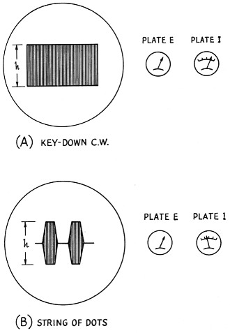
Fig. 1. (A) An unmodulated carrier looks like this on an oscilloscope.
(B) Sending a string of dots, the peak amplitude of the signal remains the same, but the plate power input will show half the steady key-down value.
In the c.w. case illustrated in Fig. 1, the peak envelope input power is the key-down input power, and the peak envelope output power is the key-down output power. We can get the peak envelope input power easily from the product of plate voltage times plate current with the key helddown, or we can get it the hard way by reading the input power when running a string of dots and dividing the indicated input power by 0.5. (Both answers will be the same when the bug is adjusted to give correct dots; "heavy" dots would require dividing by something greater than 0.5, and " light" dots would call for a divisor smaller than 0.5.) The string-of-dots case is a simple one; we divide by 0.5 because correct dots have a duty factor (pulse duration times pulse frequency) of 0.5. Dividing the indicated input power by the duty factor gives the actual power input during the "on" time.
Linear amplifiers and voice
Anyone should be able to see that it is easy to measure the input on c.w. with the key down, and not extremely difficult when running a steady string of dots (or dashes). But how would you like to be held responsible for knowing the input when all you were permitted to send was straight text? What would you use for a plate milliammeter reading? What divisor would you use?
The side-band linear case is in the same class. A typical side-band signal might show up on a scope as the sketch in Fig. 2. Most of the time the signal amplitude is at a relatively low level, but it rises to peaks during the loud syllables. If h represents the maximum amplitude the amplifier will handle without distortion (and consequent splatter), the savvy side-band operator will hold his voice at a level where these peaks are hit occasionally but never exceeded. The plate milliammeter will kick around a bit, so how do you correlate its reading with the peak envelope power (the power during that maximum peak)?
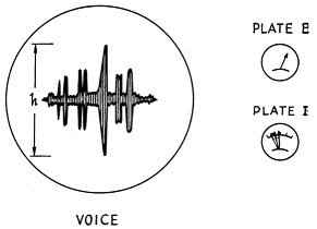
Fig. 2. Voice-modulated side-band signals look something like this on a scope. Here the height h represents the maximum amplitude that the amplifier can handle without distortion. Since the signal hits these high peaks only occasionally, the indicated power input will be low. The syllabic nature of the signal is indicated by the jumpy plate milliammeter; it bears a rather indefinite relation to the peak power input.
The FCC recognizes the problem, of course, and consequently they give us a simple requirement to meet: the d.c input shall not at any time exceed 1 kw. as indicated by meters with time constants not exceeding 0.25 second. (Time constant relates to the time it takes a meter to rise to the true value of current; a longer time constant means a more sluggish meter.)
But how do you tune up an amplifier that runs the legal limit? If a linear capable of handling the legal limit on side band is driven by a single r.f. signal to its full capability, the d.c. input will be more than a kilowatt. And, of course, while a big linear can be resonated with a single r.f. signal it can't be loaded correctly except under special circumstances (having prior knowledge of the plate current for a given level of signal).
Perhaps you have heard of the "two-tone test" and you suggest that next. No go. The two-tone test is a good method for checking the linearity of an amplifier(2); it involves using two equal-amplitude r.f. signals through the amplifier, which gives a pattern on the scope as in Fig. 3. If the pattern just starts to flatten at an amplitude of h, indicating that this is the maximum signal the amplifier can handle without generating unwanted spurious signals, the peak envelope input is the indicated d.c. power input divided by 0.636. (The two-tone signal is used because it is easy to generate and the relationship between peak envelope input and indicated d.c. power input is accurately known.) But an amplifier that runs up to the legal input on voice will run about 2 kW p.e.p. input, and an amplifier indicating 1 kW input with a two-tone test signal has a p.e.p. input of less than 1.6 kW (1 - 0.636). The two-tone test is fine for amplifiers that indicate up to 750 watts input on voice peaks, but beyond that the two-tone test on the air will result in a d.c. input of more than a kilowatt.
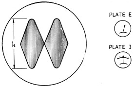
Fig. 3. The two-tone test signal applied to the linear of Fig. 2. The maximum permissible amplitude h is the same, but now the indicated power input bears a definite relationship to the peak envelope input.
Tuning a big amplifier
Obviously one way to adjust a big linear is to use a dummy load and the two-tone test signal. This is certainly the only way to work with the amplifier in the early testing stages. It will enable you to find the proper loading for good linearity and efficiency, and you can then substitute the antenna for the dummy load at reduced signal levels. But suppose you want to make a quick check on the air, or suppose you hanker to see how much you can crowd your amplifier without distortion. (Since the long-time duty factor of voice signals is perhaps 0.25 or so, and the p.e.p. input is only required occasionally, you can run the tubes harder on peaks than you might expect. But always bear in mind that you can't crowd them beyond the limits of linearity without causing distortion which generates spurious signals.)
We can't use the two-tone test continuously, so the obvious solution is to key it. This is a cinch for anyone with an electronic bug key; all he has to do is to lock the key in the dot position and key the audio tone being fed to the side-band generator. Anyone with such a bug key available can forget about the electronic pulser to be described. For those without an electronic bug, the circuit in Fig. 4 can be used to key the audio tone. It is a simple method (although the electronic bug key is even simpler, if you have one) for testing an amplifier where the ordinary two-tone test would result in exceeding the legal d.c. input limit or possible failure of the tubes.
The gadget in Fig. 4 and the photograph is not offered as a refined device for exact measurement but merely a very simple means for testing a side-band system in which the final runs at the legal limit or where the tubes are run too hard on peaks for a sustained two-tone test. It consists of a cathode follower with a.c. instead of d.c. ou the plate. A single tone (1000 cycles or so) is fed from an audio oscillator to J1 and the output is run from J2 to tho microphone jack of the transmitter under test. The follower conducts during the positive half cycles of the plate voltage and not during the negative half cycles, resulting in a test signal that is on about half the time. Since there is a 60 cycle component in the plate current, the output. is taken off through a small (15 pF) capacitor to reduce the 60-cycle component reaching the output. Most side-band transmitters will, or should, have poor 60 cycle response in their audio amplifiers, and a further reduction in 60 cycle component will be obtained.
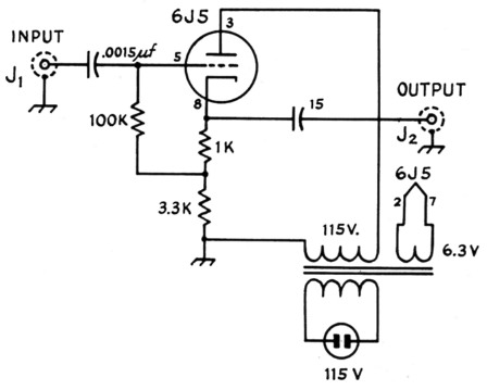
Fig. 4. Schematic diagram of a simple "pulser" for keying the audio tone used in the two-tone test. The capacitances are in pF and the resistors are ½ watt. T1 is a small TV-booster transformer (Merit P-3045 or equiv.)
Using the pulser with a typical side-band exciter and amplifier, about 2 volts of 1000 cycle audio at the input gave sufficient signal at the microphone jack to operate the transmitter. The amplifier ran 175 ma. when properly loaded for maximum p.e.p. with the two-tone test signal and 120 mA with the keyed two-tone test. The plate voltage on the amplifier was 1000 for the tests, so the maximum p.e.p., as indicated by the two-tone test, was 275 watts [1000 (0.175 / 0.636)]. With the pulsed two-tone test the indicated power input was 120 watts, and the divisor works out to be 0.44 (120 / 275). This is low enough to give less than a kilowatt d.c. input when you're hitting 2 kilowatt input peaks.
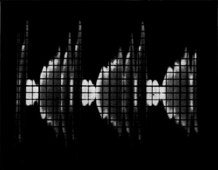
We make no claims that this is a highly-refined way to check a linear. Actually it is the simplest way we could think of (other than the bug key), and anyone who wants to derive the factor 0.44 mathematically is welcome to try it. We do claim that this is a simple gadget for pulsing the two-tone test through your amplifier and permitting maximum peaks with little strain on the tube. When you try a slow sweep on the scope, the pattern will be as in Fig. 5-A, which shows the keyed character of the signal. Some audio leaks through the pulser even when the plate voltage is negative, and that's why a small signal appears between the large ones. When a fast sweep is used, synchronized with the audio input tone, the familiar two-tone test pattern is obtained. The "garbage" around the base line is merely the signal that leaks through during the "off" time of the pulser; it wouldn't be there if the electronic hug key were used for pulsing the audio tone.
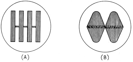
Fig. 5. (A) Pulsed two-tone test observed with slow sweep and 60 cycle sync signal
(B) Pulsed two-tone test observed with fast sweep and audio-tone sync signal.
"Crowding" a small amplifier
The fact that a speech side-band signal has a rather low duty factor permits running tubes at a peak envelope power that would burn them up under steady operation at this power. To visualize it, think of the c.w. case. You might have a tube rated at 50 watts plate dissipation, and under c.w. conditions you might run 200 watts input in Class C and never have any trouble. The tube could be operated to handle perhaps 300 watts or so, if you confined yourself to sending a short "dit" every second or so. This is obviously impractical in c.w. work, but it is closely parallel to the case we have in side-band linear operation. We can "pour the coal" to an amplifier for short periods of time if these periods are so short that the tube doesn't get a chance to overheat. The problem in side-band work is to tune up the amplifier. You have to check the peak inputs to be sure the amplifier isn't going out of linearity, and you have to hold the long-time d.c. input down to avoid overheating and tube failure. Pulsing is the answer. Using the technique described earlier, either with an electronic bug or the simple tube pulser to key the audio tone input, will enable you to get the most out of any given amplifier. Obviously an oscilloscope and a source of audio tone are required, but you really need these anyway if you are to be sure of what's happening. With small tubes and higher plate (and screen) voltage than the book says, pulse tuning of the tubes will allow the maximum output to be obtained on voice peaks without distortion. Just don't forget and whistle or sustain a tone into the mike, unless you're prepared to replace the tubes!
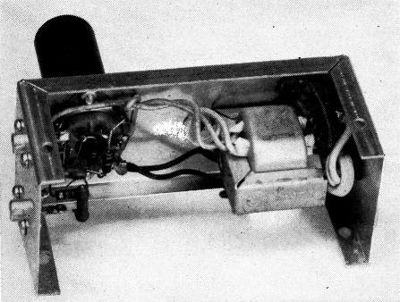
This simple "pulser" can be used to "key" an audio tone being used in the two-tone testing of linear amplifiers. A triode, small power transformer and a few capacitors and resistors are all the circuit requires.
Notes
- Generally agreed upon by manufacturers as a reasonable method of rating the power in side-band work. An explanation appears on page 20 of Single Side-Band for the Radio Amateur.
- Ehrlich, "How to test and align a linear amplifier," QST, May, 1952. Also in Single Side-Band for the Radio Amateur. If you don't understand the two-tone test, this is "must" reading. Briefly, the two-tone test involves using a single audio tone fed to a balanced modulator. The output of the balanced modulator is two side frequencies and no carrier; the two side frequencies are the two equal-amplitude r.f. signals fed to the amplifier.
The two-tone test signal is easy to obtain from any phasing-type exciter; two audio tones or one tone and reinserted carrier are required with a filter-type exciter.
Byron Goodman, W1DX.