The third method of S.S.B.
How it works in theory and practice.
Through a method of side-band folding and a.f. filtering, the system discussed here generates a single-side-band signal having the unique feature that the suppressed side band is in the same channel as the transmitted side band. This "third method," devised by D. K. Weaver, produces the s.s.b. signal directly on the desired output frequency, but does not require wide-band audio phase-shift networks.
The single side-band issue of the Proceedings of the IRE contains a thought-provoking article entitled, "A third method of generating and detecting single sideband signals."(1) The circuit is interesting in that, although the balanced modulators, filtering, and phasing are individually commonplace in s.s.b. techniques, the way they are used here is unique. It is quite unlike present practice.
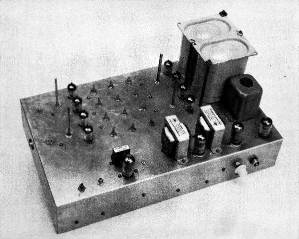
The "third method" exciter built by W1PNB was laid out for easy circuit modification during experimental work, and is therefore considerably larger than would be necessary in a "final" design. The audio circuits are along the front and the balanced modulators occupy the rear section of the chassis.
Fig. 1 is the diagram of the basic "third method" generator. A common source of audio is parallel fed to two ordinary balanced modulators. The carrier signal for these first modulators - and this is novel - is centered in the speech range at 1800 cycles. The carrier voltages are in quadrature.
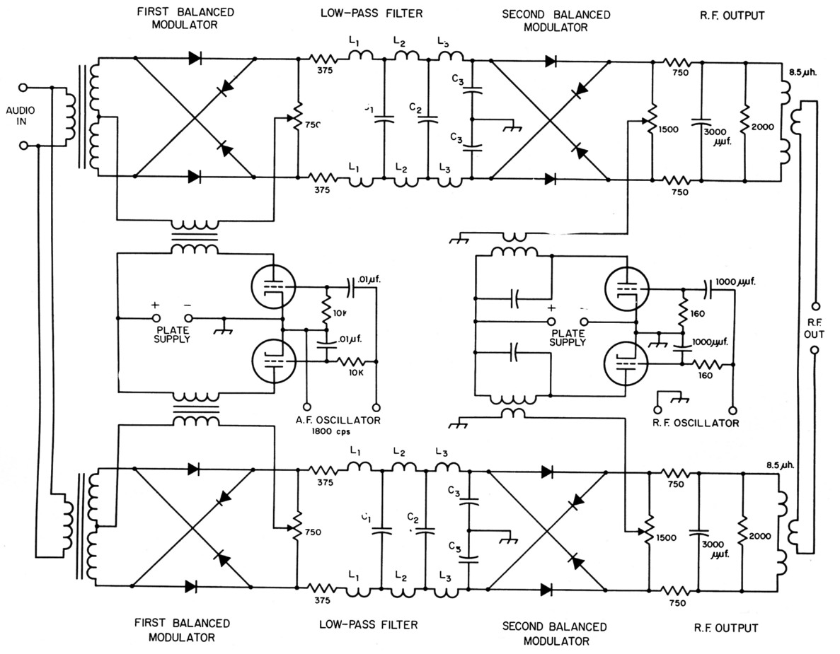
Fig. 1. Circuit of the "third method" single-side-band generator (Weaver, Proc. IRE, December, 1956). Constants of output circuits of second balanced modulators (3000 µµf. and 9.5 µh.) and the RC values in the r. f. oscillator phase-shift network (160 ohms and 1000 pF) are for an output frequency of 1 Mc. and should be modified appropriately for other output frequencies. Low-pass filter constants are as follows:
C1 0.15 µF; C2 0.20 µF; C3 0.11 µF; L1 27.5 mH; L2 100 mH; L3 75 mH.
Each modulator is followed by an identical low-pass filter designed to pass frequencies below the first carrier at 1800 cycles and reject those above that frequency.
The output of each filter feeds another balanced modulator. The quadrature carrier voltage for these second modulators is at the desired r.f. output frequency. The r.f. outputs of these modulators are combined by series connection of the links.
The circuit will be discussed further, but first let's take a look at the claims for this method:
- It does not require sharp-cutoff filters.
- No wide-band phase-shift networks are needed.
- Faulty phasing and balancing doesn't cause unwanted energy to fall outside the channel; instead, inverted in-channel energy appears.
- Undesired signal components are at least 30 db. down.
- The s.s.b. signal can be generated at any desired radio frequency.
- Operation can be bilateral; that is, the method also can be used for s.s.b. reception.
- Quality is good.
- The unit can be small and rugged.
Fig. 2 shows the speech spectrum to be applied to the system. These frequencies heterodyne (modulate) with the 1800-cycle first carrier in each initial modulator. Except for the quadrature phase shift, the outputs of both modulators are identical. For the present we need consider only one.
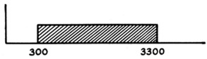
Fig. 2. Speech spectrum considered in the system described.
First Modulator and Low-Pass Filter Fig. 3 shows the output spectrum of either initial modulator. Notice that the upper side band of this modulation process (sum frequency) occupies a conventional relation to the 1800-cycle carrier, fel. The lower side band (difference frequency) is folded upon itself. This occurs because there can be no "minus frequencies" and because the carrier is within the speech range. For the latter reason there are two speech frequencies - one above, and one below 1800 cycles - which mix to produce identical frequencies in the modulator output range of 0 to 1500 cycles. This is shown graphically in Fig. 4. Here, each frequency in the difference side band may represent either of two original audio frequencies. The exception is 0 cycles (d.c.), which now represents original audio of 1800 cycles. Referring to Fig. 1, notice that d.c. coupling is used between first and second modulators so that audio information at and around 1800 cycles will not be destroyed.
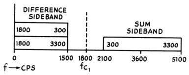
Fig. 3. Output spectrum of first balanced modulator.
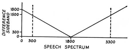
Fig. 4. Frequency components in the speech band that are spaced equally either side of 1800 cycles are converted to the same frequency in the difference side band. This occurs in the first balanced modulator.
Referring again to Fig. 3, we are interested only in the difference side band - below 1500 cycles. The sum side band - above 2100 cycles - must be effectively removed. If it is not removed this band of frequencies will appear in the final signal as a normal, readable, unfolded, "unwanted side band."
The dashed line in Fig. 5 represents the low-pass filter requirements necessary for an arbitrary 40 dB suppression of out-of-channel unwanted side band if the speech range starts at 300 cycles.
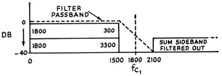
Fig. 5. Audio-frequency filter characteristic for 40db. suppression of out-of-band components.
Second modulator operation
The output spectrum passed by the filter is applied to the second modulator. In this case (the second modulator) the carrier is at approximately the desired output frequency. Quadrature phase is also maintained between the carrier voltages applied to both second modulators.
Fig. 6 is the individual output of either second modulator. The signal at this point is a doubleside-band suppressed-carrier signal. Both side bands are 1500 cycles wide. However, all 3000 cycles of original audio information is contained in each of these side bands because of the folding effect of the first modulator. Both side bands contain two components. One represents the low half of the original speech and the other, the high.
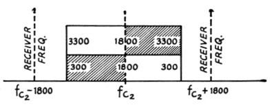
Fig. 6. The signal channel contains two sets of components, corresponding to an upper side band (shaded) or lower side band (clear). One set can be eliminated by the r.f. and audio phasing. The receiver local oscillator frequency is set 1800 cycles to one side of the suppressed transmitter carrier frequency. The side to be used depends on the side band transmitted.
Both modulators have this same output spectrum. The phase relationship of the individual outputs, due to the quadrature carrier supply to both modulators, is such that combining the outputs of the second modulators results in one component being phased out of each side band. Thus, in Fig. 6, the signal components contained in the shaded areas will be suppressed and those in the clear areas transmitted; or, if either the audio or r.f. phase is reversed, the opposite will be true. If the components in the unshaded areas are transmitted, an s.s.b. receiver tuned to a synthetic carrier frequency of 102 + 1800 will reproduce a normal audio spectrum. If the components in the shaded areas are used, the receiver would switch side bands and tune to fc2 - 1800 for proper demodulation.
Fig. 7 demonstrates the first case and shows the presence and location of the folded-back, unwanted side band. This "unwanted" is due to imperfect phasing. It occupies the same channel as the "wanted."
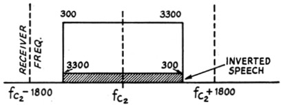
Fig. 7. An error in phasing results in an inverted side band superimposed on the desired side-band signal.
Operating characteristics
Fig. 8 is the complete output spectrum of the final signal. If the receiver is set at fc2 - 1800 or fc2 + 1800 (depending on the side band transmitted), proper reception of the original audio will result. Any unbalance in the second modulators resulting in leakage of the true suppressed carrier at fa will result in an audible 1800 cycle tone. Notice that the out-of-channel groups marked "filter unwanted" are a function of filter performance. The shaded area indicating in-channel inverted signal is a function of phasing adjustment.
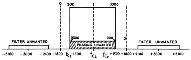
Fig. 8. Complete spectrum of the signal, showing the positions of out-of-band unwanted components not suppressed by the low-pass audio filters.
Single-frequency steady signals that tune like carriers will appear at fa - 1800 and fc2 + 1800 (the spots of proper receiver tuning) if the original audio frequency carrier at 1800 cycles is not perfectly nulled out in the first pair of balanced modulators.
The novel features of the "third method" aroused considerable interest among my s.s.b. friends. There was much speculation as to how the system would work and sound. Accordingly, having tried everything from n.f.m. to "super-modulation," I decided to give the "third method" a try. Because of uncertainty as to the outcome and a desire for cheap, speedy results, I didn't build a complete exciter but just a basic unit which could be connected to an existing exciter. The results are shown in the photograph. Since the parts were largely "scrounged" from interested bystanders and any part that would work, regardless of size or shape, was used, no conclusion as to the possibilities of the system in terms of bulk or com plexity should be drawn from the picture.
The basic circuit was followed closely. Minor changes included changing the crystal diodes to tubes, moving the output frequency to 455 kc., and changing the phase splitter of the second oscillator to critically-coupled tuned circuits. A dual triode audio stage is followed by a low pass audio filter and circuitry to attenuate lows. The 1800 cycle oscillator uses a toroid-wound inductance. The transformers supplying audio are 500 ohm line to line, and plate to line transformers supply 1800 cycle carrier. The output tuned circuits were scaled down to 455 kc.
When complete, the unit was coupled into the i.f. stages of the existing 20-kc. filter rig. The resulting signal was examined and adjustments made using the highly selective station receiver, calibrated attenuator, and oscilloscope which have been used for several years to accurately measure band width and relative amplitudes of various signal components of the transmitted and incoming signals.
The "third method" experimental exciter performed as follows: Referring to Fig. 8, the suppressed carrier at foe is nulled out by balancing the two second modulators. No difficulty was experienced in obtaining a null of at least 40 dB, but any drift in this null results in an audible whistle of 1800 cycles in the received signal.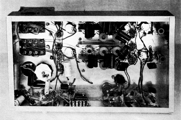
The components clustered at top center are for the low-pass filters.
The carrier-like signals 1800 cycles above and below f, l are nulled out in the first balanced modulators. Again, there was no trouble in obtaining a null. This null holds better, but the null for both signals didn't occur at exactly the same adjustment - a difficulty that was not enough to prevent obtaining a good signal. It may have been due to some peculiarity of this particular unit.
At first, considerable readable signal in the region marked "filter unwanted" was encountered. Experimentation proved that the original simple constant k low-pass filters were inadequate for obtaining out-of-channel suppression comparable to that of conventional rigs. Adding a capacitor across the center coil of the filter, to give one m-derived section, gave vastly improved results, but a better filter designed for sharpest possible cutoff is desirable. Although it is fairly easy to get the desired selectivity at this frequency, the actual slope (in cycles) must be as good as for any conventional filter rig.
When the out-of-channel problem was licked, the phasing aspect was studied. It is extremely interesting to note the effect of differing levels of folded-back side band upon wanted signal intelligibility and distortion. With no suppression of one side band, either signal can be copied, but through fairly heavy interference from the other. Thanks to the inversion of the folded-hack side band and the effects of product detection, surprisingly large amounts of unwanted signal can be tolerated without causing undue trouble. When the folded side band is suppressed 20 dB or more it seems to practically disappear as a factor in intelligibility. At 30 dB its effects on voice quality are negligible.
Conclusions
Many contacts were made using this exciter. The results were excellent. Although all desired adjustments and investigations are not complete some conclusions can be drawn from the work done.
The system is basically capable of producing excellent s.s.b. signals. Although these signals are actually double-side-band suppressed-carrier, the side-band components are so arranged that they tune like and are otherwise indistinguishable from regular single-side-band suppressed-carrier transmissions. Although the system benefits from the extremely low frequency of filter operation, and poor phasing is not ruinous, the actual attenuation vs. frequency of the two filters must be as good as in any filter rig.
The big obstacle, at the present state of design, is the complete dependence upon maintaining the null in the balanced modulators to remove the carrier and its resulting audible beat.
Although it can not be foretold what, if any, part the "third method" will play in future s.s.b. voice communication, this article is presented because this system should intrigue anyone interested in the various types of modulation.
I wish to thank those on the 75 meter band whose parts, interest, and encouragement made this an enjoyable project. The charts and graphs accompanying this article were largely prepared by Tony Sivo, W2FYT, as a result of early discussions concerning the "third method."
Notes
- Weaver, "A third method of generation and detection of single sideband signals," Proceedings of the IRE, Dec., 1956.
Howard F. Wright, W1PNB.