Transistors in speech equipment
Design notes and an all-transistor speech amplifier.
Low-level audio amplification is one spot where transistors ought to find considerable application in ham gear. Compactness and low power consumption are easily achieved. And the all-battery power supply offers an easy answer to the hum problem!
Although transistors have been on the market for some time, amateurs generally seem to be reluctant to make proper use of these extremely economical devices. This may be due to the lack of detailed circuit descriptions in amateur radio journals, and it is for this reason that this article has been written. The author will attempt to explain the design of transistorized amplifiers, and circuit details of a three-stage audio amplifier and a tone oscillator will be given.
By way of introduction, it must be emphasized that transistors can only be used within their limitations. At the present state of the art, transistors are suitable only for low-level operation. Thus in the case of modulation equipment for ham radio transmitters the speech amplifier is the first part that can be simplified, without loss of performance, by using transistors. In fact, the amplifier to be described has been used as the speech amplifier for a clamp-tube modulator, and performed satisfactorily in every respect.
This amplifier, built in the QST laboratory, uses the circuit of Fig. 2 but incorporates transistors of U. S. manufacture. The input switching circuit shown in Fig. 2 was omitted, the input coupling capacitor being connected to the microphone input terminals (a phono connector) through a 0.5 megohm resistor to provide a load for a crystal or ceramic microphone. Using G.E. type 2N107 transistors, the gain is sufficient to overdrive the last stage even though no preamplifier is used. The peak audio voltage across the secondary of the output transformer is 10 volts, with negligible distortion, using a 7.5 volt penlite cell supply. The transformer is 3 to 1 ratio interstage type with 10,000 ohm primary. It was necessary to load the secondary with a 100,000 ohm resistor to provide the proper primary load for the transistor and to minimize distortion in the last stage.
Other inexpensive transistors - General Transistor type GT-222 and Raytheon CK-722 - were used in the same circuit with similar results.
Design considerations
Engineering textbooks describe the design of transistor amplifiers in detail and readers interested in a more theoretical approach may consult them(1),(2) Although it is not intended to rehash in this article the fundamentals of transistor circuitry,(3) some introductory comments may not be amiss, with particular reference to the needs of the amateur. The design considerations of transistorized gear may briefly be listed as follows:- Care must be taken to ensure linear operation by selecting the position of the quiescent operating point.
- The circuitry has to be designed for minimum effects of ambient temperature.
- It is not advisable to operate transistors at potentials higher than the maximum data published.
The first point is well known from vacuum-tube technique, and characteristics published by manufacturers allow suitable operating points to be determined. Single-battery operation being preferable for convenience, the calculation of resistances for an appropriate bias network is outlined later.
The second point calls for some effective temperature compensation to be provided in the electronic circuitry. In other words, the bias of each stage has to be stabilized with respect to temperature variations. The effect of temperature upon transistor characteristics is considerable, particularly so far as the collector current at zero emitter current is concerned. Stabilizing circuits will be discussed below.
With reference to the third point, excessive operating voltages do not necessarily result in a complete failure of the transistor. The general performance, however, is likely to deteriorate if the transistor is exposed to such treatment. The temperature rise at the junction is a function of the dissipated power, a typical value being 0.4 degree Centigrade per milliwatt collector dissipation. The maximum junction temperature is usually given as 45 degrees Centigrade, or 113 degrees Fahrenheit. The author recalls one experiment in which the base-emitter section of a transistor was unintentionally subjected to a current far in excess of the specified limit. Subsequently, the transistor assumed a temperature of approximately 200 degrees Centigrade for a period of about three minutes. This particular transistor still performs well in a low-level oscillator, although its output is somewhat lower than before.
As is undoubtedly known to readers, there are three possible circuit connections of transistors, similar to vacuum-tube practice: common-emitter, common-base, and common-collector, resembling common-cathode, common-grid, and cathode-follower operation, respectively. Theoretical design considerations indicate that the common-base connection features lower input impedance (about 50 to 500 ohms), than the common-emitter connection (around 1000 ohms). On the other hand, the common-collector circuit provides a higher input impedance (about 60,000 ohms). So far as the corresponding optimum load impedances are concerned, typical values are 200,000 ohms, 70,000 ohms, and 2000 ohms for common-base, common-emitter, and common-collector circuits, respectively. It can be proved mathematically that, for cascade operation, the common-emitter configuration is a good compromise.
The question whether a cascade amplifier for the audio frequency range should use transformers or RC-coupling between stages is largely one of preference and availability of components. Too many transformers may cause the amplifier to become a somewhat inefficient oscillator, just as in orthodox vacuum-tube technique. Another disadvantage of interstage transformers, particularly midget transformers, may be their cost. On the other hand, straight RC-coupling results in some loss of gain, if compared with a properly matched transformer. To achieve the same gain, the mismatch between RC-coupled stages necessitates an increase in the number of stages by about 30 per cent. Also, it would seem reasonable to use additional transistors as common-collector matching stages between common-emitter amplifying stages. In practice, however, a cascade of three RC-coupled common-emitter stages provides more gain than two RC-coupled common-emitter stages with a common-collector matching stage.
Nevertheless, the common-collector configuration is a very useful connection if an input source of high impedance is to be coupled to a common-emitter transistor, as shown later in this article.
Stabilization
Fig. 1 illustrates typical bias stabilizing circuits for low-level common-emitter operation. In the first circuit, Fig. 1A, stabilization is achieved by resistance feedback between collector and base, the base current being given by the ratio of collector voltage to the resistance connecting the collector and base. In some cases, an emitter resistance may be added.
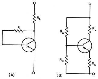
Fig. 1.Bias and stabilizing circuits for transistors.
In Fig. 1B the base bias is produced by a voltage divider RARE. The emitter resistor RE is used for automatic stabilization. This circuit provides optimum stabilization at the expense of higher over-all power consumption. It is ideally suited for low-level amplification, and has been used by the author in the amplifier to be described. Some comments on the theoretical relations of these resistors seem to be worthwhile.
A "stability factor," S, which should have a low value, is defined by(1)
where α = current amplification factor. The following formulas are used for calculating RE, RA, and RB:
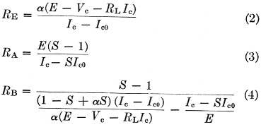
where:
RL = load resistance
E = supply voltage
VC = collector voltage at operating point
IC = collector current at operating point
IC0 = collector current at zero emitter current.
The emitter resistor, RE, has to be bypassed so that the impedance of the RC combination is negligible for all frequencies used. Omission of this bypass capacitor or the use of too low a value would result in feed-back effects similiar to those associated with the cathode-resistor bypass in tube circuits.
For completeness' sake, two other possible stabilizing circuits should be mentioned briefly. To maintain a reasonable over-all efficiency in power applications, a temperature-sensitive nonlinear device - e.g., a thermistor - is often connected into the bias network. Its characteristic enables some automatic stabilization to take place. Another possibility is the so-called tandem arrangement. This uses a resistance-stabilized transistor which supplies a constant emitter current to a second transistor. However, these circuits are not at all necessary for low-level operation, and since the amplifier under discussion is concerned with low-level audio amplification the resistance stabilization described above is quite satisfactory.
The audio amplifier
The amplifier consists of three cascaded common-emitter stages, and its circuit diagram is given in Fig. 2. The stabilizing circuits are basically identical with the one shown in Fig. l B, with an average stability factor of S = 8 for α = 0.98. The stabilization obtained is sufficient for the purpose of this amplifier. A lower factor - e.g., S = 2 - would give better stabilization at the expense of higher over-all power consumption. RC coupling is used for the input and intermediate stages and the output load is represented by the primary winding of an ordinary interstage transformer. Its secondary is connected to the modulator stage, or any other load.
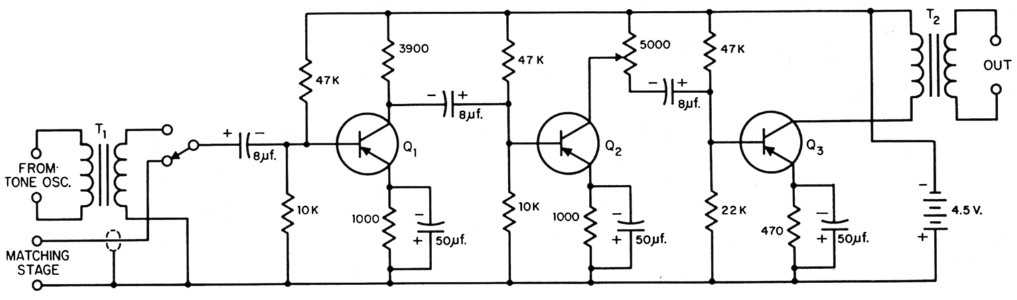
Fig. 2. Circuit of the all-transistor speech amplifier. Capacitors are electrolitic, 25 volt or lower rating sufficient. Fixed resistors are ½ watt.
| Q1 | Philips OC-71. |
| Q2,Q2 | Philips 0C-72. |
| T1 | Interstage audio, 2 or 3 to 1 ratio, larger winding connected to tone-oscillator terminals. |
| T2 | Interstage audio, about 3 to 1 ratio, larger winding connected to output terminals. |
The transistors utilized are Philips junction triodes OC-71 and OC-72, all operated in Class A. As is general practice with transistor amplifiers, appreciable coupling capacitance must be used to suit the generally low input impedances of transistor stages. Each stage has been carefully designed to provide optimum amplification at the general supply voltage of 4.5 volts, which is taken from a flashlight battery. At the current consumption of 3 to 5 ma. for the entire three-stage amplifier, the life of the battery should be nearly equal to the shelf life.
The last two stages of the amplifier are equipped with OC-72s. These are classified as medium-power transistors, with a permissible dissipation power of 45 milliwatts. In Australia they are commercially available in matched pairs for Class B power operation. However, their characteristics are such that they are also very suitable for single Class A operation, as used in the amplifier under discussion. Of course, OC-71s could be substituted which would result in somewhat less amplification.
Using the primary of an ordinary audio interstage transformer as the output load, the input impedance at the base of the first stage is of the order of 1000 ohms.
A volume control has also been included. As is evident from the circuit diagram, the load resistor of the second stage has been made variable for this purpose.
Input matching
The relatively low input impedance of the amplifier requires a matching network of some kind. Dynamic microphones can be matched easily by a suitable transformer. In the case of crystal microphones a special matching stage appears to be the best solution.
As mentioned earlier, a transistor in the common-collector configuration is suitable for matching a high to a low impedance, in analogy to the cathode follower in tube technique. However, with a load impedance of about 1000 ohms the input impedance of this circuit is of the order of 60,000 ohms. This is still a bit too low for adequately matching a crystal microphone, although the position is definitely improved. The remainder of the load has to be provided by a resistor, resulting in a loss.
Another solution is the use of a common-emitter stage with appreciable resistance in series with the input, in order to match a high-impedance source. The loss in the resistive element is compensated for by the amplification of this stage so that an adequate signal appears at the output of the matching stage. Fig. 3 is the complete circuit diagram of such a matching stage, as used to match a crystal microphone to the input of the three-stage amplifier.
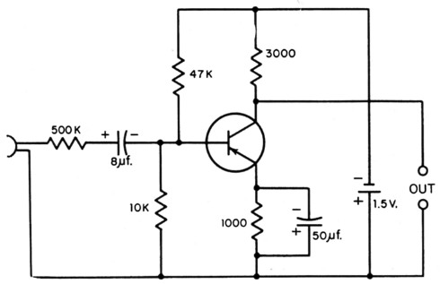
Fig. 3. Preamplifier circuit for coupling a crystal or other high-impedance microphone to the speech amplifier.
Tone oscillator
A detailed description of this part is not necessary, as circuits of transistorized tone oscillators or code-practice oscillators have been published in ham radio journals from time to time. Fig. 4 shows two popular LC feedback oscillators. In vacuum-tube practice these oscillators are known as the Colpitts (A) and Hartley (B), respectively.
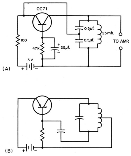
Fig. 4. Audio oscillator circuits. The upper, a "Colpitts," will generate a tone of about 1000 cycles per second. The "Hartley" arrangement is shown below for comparison.
For m.c.w. and test purposes, an oscillator of the type depicted in Fig. 4A has been included ill the amplifier under discussion. An old Siemens r.f. iron-core coil of 1940 vintage was found to be extremely useful. A maximum number of turns was wound on the three sections of the core (total dimensions: diameter 0.88, height 0.72 inch), resulting in an inductance of approximately 25 millihenrys. The smallest capacitor that could be detected anywhere was also found in the junk-box. It is a center-tapped Bosch metallized-paper capacitor of 1 microfarad, another German disposals components (the author is ex-DL3EC). Of course, both parts can easily be replaced by modern components. Two penlight cells make an appropriate power supply and last for a considerable period at a maximum consumption of 2 milliamperes. The frequency of oscillation is of the order of 1000 cycles per second.
An interstage transformer (about 2.5 to 1, the higher impedance side toward the oscillator) is used to couple the oscillator to the input of the amplifier (see Fig. 2). A double-pole switch at the amplifier input selects the secondary of the transformer or the microphone matching stage.
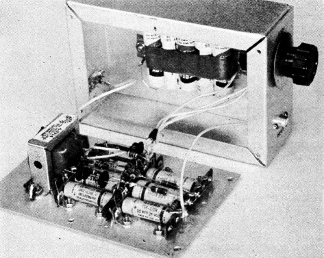
Constructional details
A small chassis was used as a the container for the amplifier and its 4.5 volt battery, the oscillator being mounted on top of the chassis. The crystal-microphone matching stage was housed in a small box which also contained its supply, a 1.5 volt dry cell.
The entire setup must be well shielded, particularly if used in connection with a transmitter, in order to counteract any possible r.f. feedback. Likewise, the output cable and the cable from the matching stage must be shielded.
Performance
In the several months during which the equipment described in this article has been used its performance has been satisfactory in every respect. In the case of the author's ham station, the unit has been employed as a speech amplifier, its output being connected to the grid of a controlled-carrier modulator, a 12A6, which is used to modulate the p.a. (90 watts input, home-built, pair of 807s). The modulation level obtainable allows a fair amount of volume reserve. The output signals of the microphone matching stage and of the oscillator are of the same order of magnitude, permitting a convenient change-over from m.c.w. to telephony.
Notes
- Shea, Principles of Transistor Circuits, Wiley, New York.
- Terman, Electronic and Radio Engineering, McGraw-Hill, New York.
- Basic principles were discussed by Priebe, "Transistor operating characteristics," QST, Feb., 1957. - Ed.
Hans J. Albrecht, VK3AHH.