Greater selectivity with the c.w. clipper-filter
A two stage amplifier with variable band with.
By adding a second stage to the c.w. clipper-filter described in an earlier issue of QST, W1PLM obtains a band width of 200 to 600 cycles at 40 db. down. A simple method of varying the selectivity is included.
The modernized version of the c.w. clipperfilter described by W1CUT in QST(1) is an improvement over that originally described by Grammer? However, for c.w. work on today's crowded bands its selectivity is still inadequate. A band width of 100 cycles at 6 dB down does not sufficiently attenuate adjacent signals if the band width at 40 dB down is one to two kc. What is required is a band width of the order of 300 to 500 cycles at 40 dB down.
This band width is easily achieved by means of the audio filter described by W1CUT; it only requires the addition of one more stage of filtering, exactly similar to the first stage, and tuned closely to the same frequency.
Inductors
Fig. 1 shows the circuit with the added filter stage. The W1CUT technique of using small power-supply chokes was followed quite successfully except that the bar of "I" laminations lying across the top of the "E" laminations was not removed entirely. Instead, 3 to 5 layers of paper were put between the "E" laminations and the bar of "I" laminations and a nonmetallic clamping arrangement, such as shown in Fig. 2, was used to hold the assembly. The inductances, and hence the resonant frequencies, can now be adjusted by tightening or loosening the clamping screws. The Q of the chokes seems to be about the same with the air gap increased in this manner as with the "I" laminations removed altogether. Two similar chokes should be used so that their series-resonant frequencies will be close to one another when altered as described.
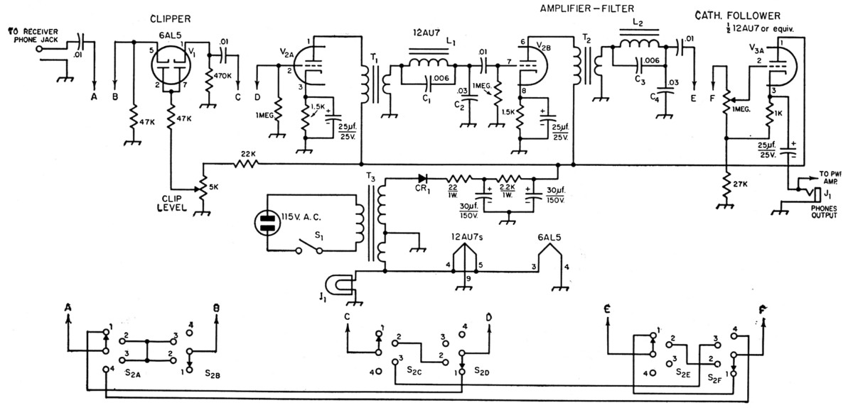
Fig. 1. Circuit of the two-stage clipper-filter. All capacitances are in nf. All 0.01 µf. capacitors may be ceramic; capacitors marked with polarity are electrolytic. Others should be tubular plastic or mica. Resistors are ½ watt unless otherwise specified. Switch functions are as follows: Position 1, dual filter alone; Position 2, clipper and dual filter; Position 3, clipper alone; Position 4, straight through with cathode-follower output.
| CR1 | 50 mA selenium rectifier. |
| I1 | 6.3 volt pilot lamp. |
| J1 | Open circuit phone jack. |
| L1,L2 | 5 H 65 mA filter choke; frame removed and choke remounted as described in the text. |
| S1 | S.p.s.t. toggle switch. |
| S2 | 3 section 6 pole 4 position rotary switch, shorting type preferable. (Centralab PA-1020). |
| T1,T2 | Output transformer: 7000-10,000 ohm primary to 3.2 ohm voice coil (Thordarson 24S52). |
| T3 | Power transformer: Half-wave: 125 V, 50 mA; 6.3 volts, 2 amps. (Stancor PA-8421). |
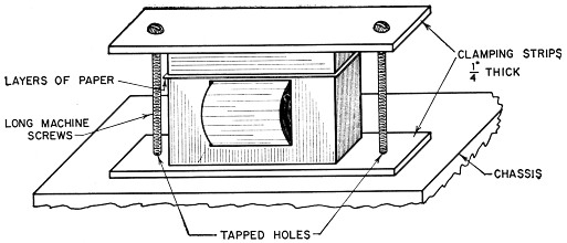
Fig. 2. Sketch showing the method of clamping and tuning the filter inductors. Clamping strips must be of bakelite, phenol, plastic or other suitable insulating material. Metal should not he used.
Circuit
Two changes were made in the switching circuits described by W1CUT. The first position of the switch was changed from filter-clipper to dual filter alone. This seems to offer a characteristic much more useful to this writer than did the filter-clipper characteristic. The receiver output in the straight-through position is connected to the output through the cathode follower. The writer also incorporated in his unit a simple beam power-output stage to drive a speaker.
Characteristics
The selectivity curves obtained from the unit are shown in Fig. 3. The two series-tuned circuits, L1C2 and L2C4, cannot be tuned to exactly the same frequency because excessive ringing results. The two circuits may be tuned about 10 cycles apart, resulting in a very sharp characteristic as shown by Curve 1. A more easily-used characteristic is shown by Curve 2 in which the tuned circuits are tuned about 30 cycles apart. Curve 3 results with the two circuits tuned about 60 to 70 cycles apart and is almost flat-topped, but it still has fairly steep skirts. The notch frequencies, governed by L1C1 and L2C3, were set higher than those used by W1CUT, while the peak frequencies were set to about 700 cycles, an audio frequency more pleasing to the writer than 900 cycles.
It should be mentioned that the 0 dB reference is not the same for the three curves. If the peak of the sharpest curve is taken as 0 dB, the peaks of the progressively less-selective curves fall short of 0 dB, by increasing numbers of dB. In other words, the signal loudness increases with increasing selectivity until limited by ringing. It should also be noted that the response characteristic is effectively broadened by overloading signals. The receiver r.f. gain control thus should be backed off considerably when the desired signal is tuned in; the tremendous gain of the filter at the peaked frequency will allow the desired signal to be easily copied while, in most cases, all other signals will be inaudible.(3)
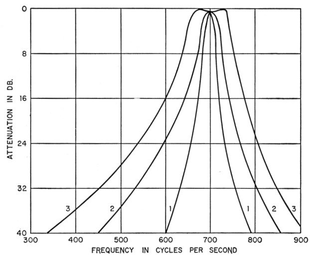
Fig. 3. Selectivity curves of the two-stage filter of Fig. 1. Curve 1 is with the circuits tuned about 10 cycles apart; Curve 2, 30 cycles apart; Curve 3, 60 to 70 cycles apart.
It is immediately evident that variable selectivity is easily obtained by altering the capacitances of C2 and C4 by means of a two-gang multicontact switch. Capacitance is progressively added at C2 and subtracted at C4, thereby broadening the selectivity curve while maintaining the center frequency. Fig. 4 shows one simple method of achieving this.
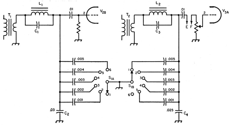
Fig. 4. One method of achieving variable filter selectivity. Greatest selectivity is obtained with S1 in Position 1. All capacitances are in µF, and capacitors should be plastic tubular or mica. C1, C2, C3, C4, L1, L2, T1 and T2 refer to Fig. 1.
Adjustment
The filter can be aligned with the help of an audio signal generator and a scope. If C2 and C4 are to be fixed, the procedure is to set the two tuned circuits individually to within 10 to 15 cycles of the chosen peak frequency, but on opposite sides of that frequency. This adjustment can be made by tightening or loosening the clamping screws on each choke until each circuit is tuned to the desired frequency. Altering the number of layers of paper placed between the "I" and "E" laminations of either or both chokes will allow any two similar chokes which, due to manufacturing tolerances, may be of slightly different inductances, to be tuned to the same frequency. The filter is then ready to go. If the response is too sharp, slightly greater separation of the two frequencies can be achieved by a readjustment of the clamping screws on one of the chokes.
If the switch is to be used to obtain variable selectivity, the procedure is equally simple. With the switch in Position 1, the chokes are adjusted so that the respective series-resonant frequencies are 10 to 20 cycles apart, depending on the desired sharpness in the sharpest position. Then for switch Positions 2, 3, 4, etc., one switch section successively substitutes capacitors smaller by 0.001 µF in parallel with C4, while the other section successively increases the capacitance in parallel with C2 in increments of 0.001 µF. The resonant frequencies of the two circuits thus move about 10 to 15 cycles farther apart for each succeeding position until the minimum de sired selectivity is reached. At about 70 cycles separation, a dip appears in the center of the flat-topped portion of the curve, and at separations beyond 100 cycles this dip in the characteristic is severe enough to limit the usefulness of less-selective curves.
If no equipment is at hand, the circuits can be tuned by listening tests only. One's own c.w. signal can be used as a substitute for the audio signal generator. There will be no doubt when the two series-tuned circuits become resonant at close to the same frequency.
As mentioned in the original article(1), symmetrical output wave form depends upon proper choice of resistances in the diode circuit. The values shown were used after checking on an oscilloscope.
The operating difference between a clipperfilter using one tuned stage and one using two tuned stages is like the difference between night and day. The signals pop in and out and are best tuned by means of the beat-oscillator pitch control. Most such controls cover 2 to 3 kc. and are ideal for tuning over a narrow region around your own operating frequency.
Notes
- Campbell, "Modernizing the c.w. clipper-filter," QST, December, 1956, p. 36.
- Grammer, "An accessory for c.w. reception," QST, July. 1950, p. 11.
- This is indicative of regeneration which undoubtedly contributes to the selectivity. - Ed.
L.I. Albert, W1PLM.