The effect of capacitance on power supply filter bounce
A discussion of power supply dynamic regulation.
The fact that the output voltage of a power supply decreases with an increase in load current is universally appreciated, hut relatively few amateurs are aware of the rather drastic changes in output voltage that can occur when the load is rapidly varied, as in c.w. keying or in s.s.b. work. This article shows graphically how the output voltage is affected by the resonant frequency of a choke-input filter, and how the situation is improved by going to a large output capacitance. The effect of the filter constants on the surge currents that occur when the supply is turned on also is shown.
Load changes affect power-supply output voltages, regardless of the quality of design and components used. Some of the drop in output voltage with an increase in load is caused by rectifiers or resistance, and some of these factors are discussed here; but the most annoying and alarming current or voltage change - and the least well-known - is "bounce" or "resonant response." Resonant response in a power-supply filter is a simple process, and it is hoped this discussion will show how simple it is.
Why filter a rectifier?
A rectifier changes alternating current to "one-way" current (not direct current) by choosing paths through the rectifying circuit that only let the output current flow in one direction. The output current may be large or small; it may even be zero if there is no possible path for current to flow in that one favored direction. Half-wave, full-wave center-tap and full-wave bridge (single-phase) rectifiers without filtering all produce zero voltage many times each second. The half-wave voltage peak is more than three times the "d.c." (average) voltage, while full-wave peaks are more than one and a half times the "d.c." voltage, as shown in Fig. 1.
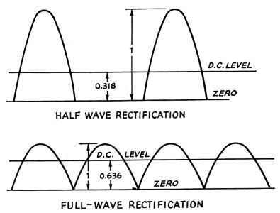
Fig. 1. Comparison of half-wave and full-wave rectification. The value of the average (d.c.) output is shown referred to the peak value of the rectified wave, neglecting any tube and resistance drops.
These unfiltered current or voltage waves from the rectifier actually (and mathematically, too, but not here) can be considered to be made up of a constant, smooth "one-way" (direct) current plus several alternating-current waves. If constant, smooth direct current or voltage is wanted, the alternating current waves must be greatly reduced. The best filter reduces the a.c. without affecting the d.c.
Alternating current waves produced by halfwave rectifiers have frequencies equal to whole numbers (1, 2, 3, etc.) times the supply frequency; such as, 60, 120, 180 cycles per second for a 60 c.p.s. supply. The lowest frequency has the largest wave and is hardest to filter.
Perfect full-wave rectifiers produce alternating currents whose waves have frequencies even whole numbers (2, 4, 6, etc.) times the supply frequency. A full-wave or bridge rectifier powered from a 60 cycle power line will produce smaller amounts of the more easily filtered 120, 240, 360 cycle and higher frequency waves. (But one should not forget unbalanced tubes or transformers will produce a 60 cycle wave, in addition, in the output.)
What's a filter?
A filter is a circuit that passes electrical waves in desired proportions. A steady one-way current does not change and can be said to have no cycles per second, so wherever "frequency" is used in the arithmetic, the number zero can be used as the frequency of the steady current.
A filter prevents or reduces passage of electrical waves either by changing the electrical energy to heat in a resistance or by providing a path that will not accept energy from waves of certain frequencies. A wave of any frequency (even zero) loses energy in passing through a resistance, so in a power-supply filter it is usually best to use parts and circuits having as little resistance as practicable. This means that circuits using chokes and capacitors are most efficient in selecting the desired direct current while reducing the accompanying a.c. waves to acceptable levels. Since more than twice as much inductance-timescapacitance (L × C) is required to filter halfwave rectifiers as full-wave rectifiers, only full-wave rectifier filtering will be discussed.
Capacitor or choke input?
The most commonly used filter is the capacitor-input type, Fig. 2A, sometimes also called the "brute-force" or pi (π) filter. Good quality input capacitors (the only kind that will work and last in this filter) permit extremely high pulse currents to flow through the rectifier. These currents are limited only by tube drop and power transformer impedance. It is costly to design good life into this circuit.
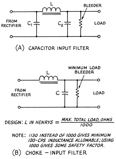
Fig. 2. Capacitor and choke-input filters. "Minimum" load corresponds to maximum resistance (bleeder only); "maximum" load to minimum total resistance across the supply.
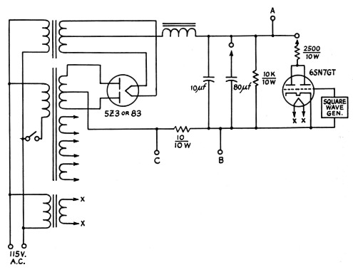
Fig. 3 - Test setup for checking filter "bounce" with changes in load. The 6SN7GT acts as a switch for alternately connecting and disconnecting the load, when its grids are driven by a square-wave generator. For observing voltage changes the vertical plates of the oscilloscope are connected to A and B. The rectifier input current can be inspected by connecting the oscilloscope to C and B. The setup uses a receiving-type power transformer and filter components.
Changing the drain on the supply changes the output voltage. Fig. 4 shows both the inrush current (when the power is turned on) and the output voltage change with load for a typical capacitor-input filter. This filter used 10 µF input and output capacitors and a 10 henry, 45 ohm choke. Much less voltage drop with load can be obtained with a choke-input filter, Fig. 2B.
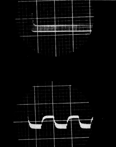
Fig. 4. Top: Inrush current through rectifier tubes to capacitor-input filter. Left-hand end of trace represents instant of closing power-line switch. The trace consists of a series of pulses at the rectified-output frequency (120 cycles per second) each of which is a pulse of current into the first filter capacitor, the peak current being represented by the height of the pulse. (Note that alternate pulses are not quite the same height, indicating that the outputs of both sides of the rectifier are not quite equal.) The inrush surge current has a peak about three times as high as the steady-state pulses, and takes several cycles to die away.
Bottom: Change in d.c. output voltage with change in load; load switching at a uniform rate. Ripple voltage in the output is indicated by thickening of the trace; the ripple increases with heavier loading, as shown by the fact that the lower sections of this trace, representing lower d.c. output voltage, are thicker.
Other advantages of choke-input filters include low "runing peak currents" to prevent damage to rectifier tubes and filter capacitors. The most common (and wrong) objection to choke input is that "capacitor input gives more power out of the power transformer!"(1) One manufacturer(2) puts out two power transformer lines, one for choke input, one for capacitor input. For equal d.c. output voltages and currents, cost, size, and weight are nearly identical. In no known case are high-voltage, high-power transformers made for capacitor-input filters.
How Much Capacitance?
Inrush or surge currents with choke-input filters may be quite high.(3) RCA recommends certain choke and capacitor values, specifying that if the capacitance is increased, the inductance must be increased the same proportion. The effect on surge current is shown in Fig. 5. The lower oscillogram is the surge in a 10-henry choke-input filter with 10 µF capacitance. The upper oscillogram shows the effect of 40 henrys and 40 µF. (This second photo is not to the same scale as the capacitor-input photo, Fig. 4.) If the capacitance is increased without increasing the inductance, the situation shown in Fig. 6 results. The upper picture shows the surge with 10 henrys and 10 µF; the lower shows the effect of increasing the capacitance to 90 µF.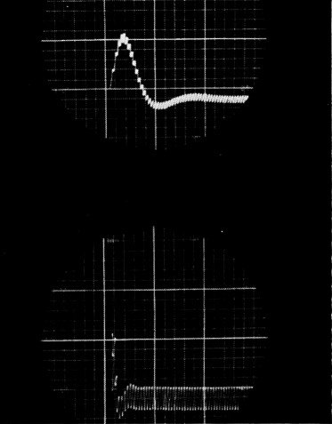
Fig. 5. Inrush current through rectifier tubes to choke-input filter. Top: 40 henry input choke followed by 40 µF capacitor; bottom: 10 henry input choke followed by 10 µF capacitor. Note that the maximum surge current is the same in both cases (somewhat more than twice the steady-state current) since the L/C ratio is the same, but that its duration is dependent on the amounts of L and C in the filter. The a.c. ripple in the rectifier output current is considerably smaller in the filter with the larger LC product.
With the choke-input filter the rectifier output current does not go to zero between pulses of rectified current. Compare these photos with the top picture in Fig. 4, where the rectifier output current consists of a series of discrete pulses separated by periods of zero current. (The latter is represented by the bright base line in the upper photo of Fig. 4.)
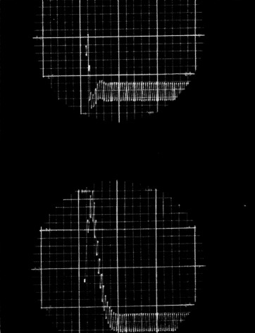
Fig. 6. Effect of changing L/C ratio on inrush current to rectifier tubes through choke-input filter. Top: 10-henry input choke followed by 10-4. capacitor; bottom: 10-henry input choke followed by 90-4 capacitor. The scale in these photographs is the same as in Fig. 5.
The peak inrush current is considerably larger with the larger capacitance (smaller L/C ratio) and has a greater duration because of the larger LC product. Note also that the small oscillation or overshoot at the terminal end of the transient is practically eliminated with the larger capacitor.
No surge problem exists, of course, if the plate power transformer voltage is turned on gradually and left on. (This assumes that the energy stored in the filter much exceeds the variable demand.)
Load change does affect the output voltage of choke-input filters. Fig. 7 shows the effect on the output voltage of switching a resistive load (Fig. 3) on and off the filter output at 5, 15, and 45 times per second. There is obviously resonance at 15 times per second, in very close agreement with the resonant frequency of the 10-henry inductance and 10 µF capacitor used. Fig. 8 shows an enlarged picture of the 5-times-per-second switching rate.
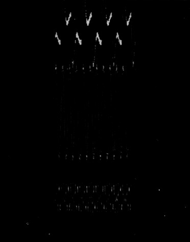
Fig. 7- Filter resonance effects in output voltage as a load is alternately switched on and off; choke-input filter with 10 H choke and 10 µF capacitor. Top: load switched at rate of 5 times per second; center: switching rate 15 per second; lower: switching rate 45 per second. The large swing in output voltage in the middle photo is caused by the resonance in the filter, its natural resonant frequency being approximately the same as the switching rate.
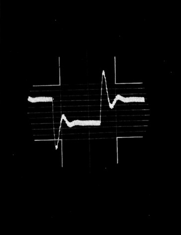
Fig. 8. Load switching at 5 cycles per second with expanded sweep in the oscilloscope, same conditions as Fig. 7. The output voltage tends to oscillate at the resonant frequency of the filter, 15 c.p.s.
Increasing the capacitance to 90 µf. almost completely removes the overshoot. This is shown in Fig. 9 (5-times-per-second switching) and the Fig. 10 (twice a second switching). It is felt that the lower Q at the "predicted" 5 cycle resonance frequency is responsible. High capacitance does remove load bounce from the voltage output.
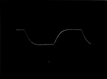
Fig. 9. Output voltage switched at 5 cycle rate, choke-input filter using 10 henry choke and 90 µF capacitor. The overshoot visible in Fig. 8 is practically entirely gone. (The improved ripple smoothing resulting from the use of the larger value of capacitance is also evident on comparison of this photo with Fig. 8.)
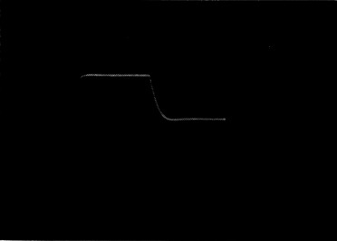
Fig. 10. Same filter as in Fig. 9, but with load switched at a 2-cycle rate.
Recommendations
No detailed recommendations can be given - there are too many possible situations - but the following suggestions should be helpful:
Reduce surge currents by turning on rectifier plate voltage gradually and leaving it on. Do not try to find chokes of extreme inductance (at $15 to $30 per watt-second).
Use choke-input filters for medium- and high-power supplies. Use of high capacitance will minimize filter voltage bounce and produce sufficient hum filtering.
Remember that all supplies not electronically regulated will show some voltage change with load. If very stable voltage is required, an automatic voltage control system must be used.
Acknowledgments
Thanks are due Harold Churchill of the Signal Corps Engineering Laboratory for asking the question that initiated this investigation. Prior writers in this field shortened the labor by clear reporting and deserve credit. The permission, assistance, experience, and advice of the Sprague Electric Company team has also been essential.
Notes
- Probably because the d.c. output voltage from the same transformer-rectifier system will be higher when a capacitor is added in front of a choke-input filter. This neglects transformer heating, which is higher for the same d.c. power output with capacitor input than it is with choke input, even though the output voltage is lower with choke input. - Ed.
- Chicago Standard Transformer Corp.
- RCA Tube Handbook HB3, Vol. 9-10, p. 866-A/866, 6/30/44.
David T. Geiser, W1ZEO.