A radio telescope
For the sun, the radio stars, and the earth's artificial satellite.
The antenna system described here is a type suitable for tracking the Earth Satellite. provided there is sufficient spacing (500 to 1000 feet) between elements. The receiving method discussed has been developed to separate star noise from ordinary background noise and, while it ..outd be simplified a bit for the c.w. signal to be transmitted by the satellite, is well suited for calibrating a satellite-tracking antenna as described in April QST.
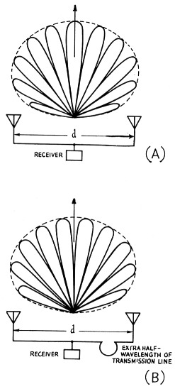
Fig. 1. Reception patterns of radio interferometers. In A the two antenna elements are connected together with equal lengths of transmission line. The resulting pattern has a maximum in the plane of symmetry of the two elements. In B the two elements are connected together out of phase, resulting in minimum sensitivity in the plane of symmetry.
One of the simplest methods of detecting radio sources in the sky, whether astronomical or artificial, is by use of a radio interferometer. The system to be described in this article is similar to systems used by radio astronomers in various parts of the world during the last ten years for detecting radio stars and measuring their positions, as well as for studying the radio emission from the sun.
An antenna consisting of two elements (where each "element" may be a dipole, Yagi, or other array) separated by several wavelengths will have a pattern which is broken up into many lobes. For example, the antenna shown in Fig. 1A will have a pattern somewhat like that shown above it. The envelope of the pattern (dotted line) is determined by the elements at each end of the system, while the angular spacing of the lobes is determined by the spacing of the elements (length d in Fig. 1A). The angle between the centers of two adjacent lobes is about 60 λ/d degrees, where λ is the wavelength measured in the same units as d.
If we add an extra half wavelength of transmission line to one side of the antenna system, as indicated in Fig. 1B, the pattern will be similar to Fig. 1A, but the lobes will all be shifted in angle by half of their width. The envelope will be unchanged. This new pattern is also pictured in Fig. 1B. If further we arrange to put in and take out this extra half-wave length of line, we can switch between the two patterns of Fig. 1. A radio star, satellite, or other source which is at a maximum of the pattern when the half wave length section is out will be at a minimum when the extra piece is in. If we then switch the half-wave-length section in and out at a rate of, say, 1000 times a second, the output of the receiver will contain a 1000 cycle component caused by the presence of the radio star or source. The 1000 cycle modulation on the signal easily can be amplified and detected and used to indicate the presence and position of the radio star. The position is obtained from the phase of the 1000 cycle modulation relative to the switching cycle.
Antenna Considerations
Now the question arises as to what sort of antenna-receiver combination we can build to do all this. First we will take a look at the antenna. It is possible to detect the sun and several radio stars with an antenna consisting of just two half-wave-length dipoles at any frequency from about 15 Mc. up to well above 108 Mc., the satellite frequency. In Fig. 2 is an actual record from a pair of dipoles and a receiver such as we will describe, operated at 108 Mc.(1) The record shows the up-and-down variations of the receiver output as the rotation of the earth carries the sources through the lobes of the antenna pattern. At the left end of the record are variations caused by the strong radio source in the constellation of Cygnus. Near the center of the record the Cygnus wiggles become confused with wiggles caused by the even stronger source in Cassiopeia. At the right the sun takes over and dominates the record. One can see from this record the disadvantage of using a single dipole for the antenna element or, in fact, using any type of element which gives a broad envelope to the antenna pattern. Several radio stars can be in the over-all antenna pattern at one time, resulting in a somewhat confused record. The second record in Fig. 2 indicates the improvement achieved by using higher-gain antennas (sharper pattern). Here the two strong radio sources are completely separated and can be studied individually.
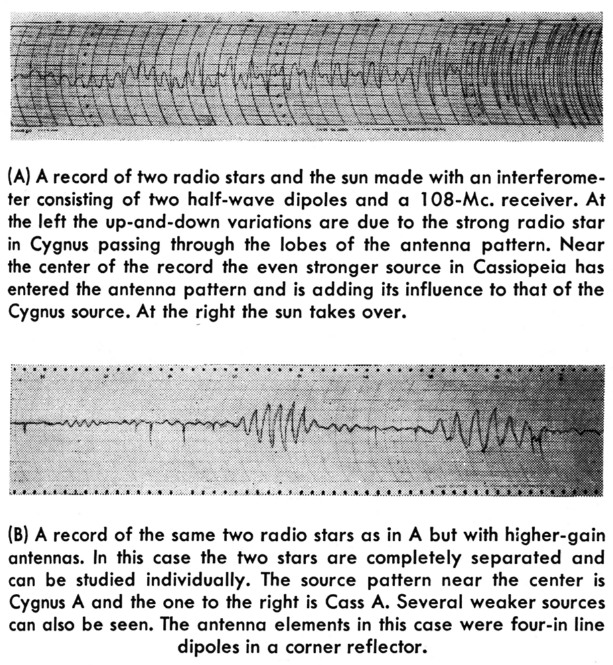
Fig. 2.
(A) A record of two radio stars and the sun made with an interferometer consisting of two half-wave dipoles and a 108 Mc. receiver. At the left the up-and-down variations are due to the strong radio star in Cygnus passing through the lobes of the antenna pattern. Near the center of the record the even stronger source in Cassiopeia has entered the antenna pattern and is adding its influence to that of the Cygnus source. At the right the sun takes over.
(B) A record of the same two radio stars as in A but with higher-gain antennas. In this case the two stars are completely separated and can be studied individually. The source pattern near the center is Cygnus A and the one to the right is Cass A. Several weaker sources can also be seen. The antenna elements in this case were four-in line dipoles in a corner reflector.
An antenna which will provide enough gain for picking up the rather weak signals from the satellite can be made of two 8-dipole broadside arrays spaced as far apart as the available ground will permit. Fig. 3 shows the arrangement as seen from above. Each dipole is supported by two posts driven or set in the ground and backed up by a simple ground screen. The dipoles themselves are folded half-wave dipoles constructed of ordinary TV Twin-Lead. Fig. 4 gives the details of the construction, and Fig. 5 diagrams a feeder system to get all eight dipoles connected in parallel. It is important that all the dipoles be phased correctly - that is, the leads to the north ends of all the dipoles are connected together and the leads to the south ends are all connected together.
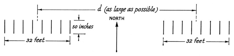
Fig. 3. Arrangement of possible interferometer as seen from above.
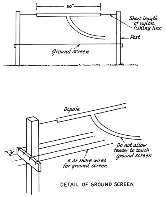
Fig. 4. Construction details of antenna.
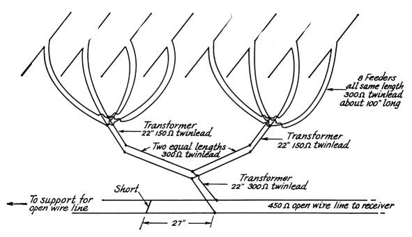
Fig. 5. Feed system for antenna.
For the long transmission line connecting the two arrays to the receiver, 450-ohm open-wire line is convenient and sufficiently low loss. If the commercial variety is used, remove most of the separators, leaving only one every four or five feet. This procedure seems to make the line less sensitive to moisture. For a nicer line, No. 14 wire stretched tight and supported only every thirty or forty feet works well. For 450 ohms, the No. 14 wire should be spaced about 1.4 inches. This type of line has been used on arrays up to 2000 feet long at 300 Mc. and has proved satisfactory except when rain is actually falling.
At the center of the line two baluns must be used to put the signal into coax for entering the house, shed, shack, or what have you. The arrangement near the center is shown in Fig. 6. The arrangement as shown is slightly mismatched at the balun. If better matching is desired, the spacing of the open-wire line could be gradually decreased during the last 30 or 40 feet so that it is about ½ inch at the balun.
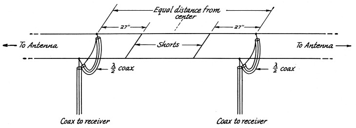
Fig. 6. Detail near the center of the transmission line.
The two arrays should he placed on as accurate an east-west line as can be determined with the available equipment. Furthermore, all the dipoles should be at the same level. Although interferometers not built on east-west lines or not level can be used, it is much harder to analyze the final measurements and determine the position of the satellite.
In the simplest case, when the interferometer is both level and on an east-west line, the central lobe of the antenna pattern lies on the meridian. That is, the maximum response of the pattern coincides with a line in the sky passing through the north pole, the point directly overhead, and the point directly to the south. From the output record one can measure the time at which the satellite or other signal source was on this line. The position of the object is thus not completely specified, but if a number of different observers can give lines on which the source lay at various times then the true position and orbit can be calculated.Receiving equipment
A block diagram of the receiver to be used with this antenna is shown in Fig. 7. Most of the items are well known and need little description. The r.f. amplifier can be any of the low-noise preamplifiers which have been written up in QST. Our preference is a 6AN4-6AN4 grounded-grid model similar to that described by Simas.(2) But do not work too hard for that last dB of noise figure. The sky contributes about 10 dB of noise, so any preamp with a 4 dB noise figure is good enough. The oscillator for the mixer must be crystal controlled.
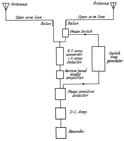
Fig. 7. Block diagram of a phase-switching radio interferometer.
The i.f. amplifier and detector are standard items and could be a good communications receiver. The gain needed is about 120 dB for r.f. plus i.f. when observing the satellite. About 10 dB less will do for the radio stars. The U. band width should be 10 kc. for the satellite and as wide as possible for the stars. Probably one will he limited by interfering stations to a 100 kc. band pass.
The narrow-band audio amplifier is just an audio stage with a voltage gain of 100 or so and a simple L-C filter to limit the band pass to the neighborhood of the switching frequency. This could be part of a communications receiver.
The switch-frequency generator is an audio oscillator with two push-pull outputs, one of which can be shifted in phase relative to the other. One of the outputs needs to be pretty husky and will be mentioned again.
Phase switching
The phase switch, or the unit that puts ici and takes out the extra half-wave length of line, is an item which will be new to most hams. However, it can be made simply, and in Fig. 8 a form of phase switch is shown which is mostly pieces of coaxial cable either ¼ or ¾ wavelengths long. The actual switching is done by two high-conduction crystal diodes. The switch is built on a sheet of copper or aluminum, and the braid at each end of each length of coax is strapped or soldered to the sheet. The photograph (Fig. 9) shows the type of construction used. To provide the rather large switching current required by the diodes (50 mA), a circuit such as that shown in Fig. 10 will be needed to amplify the output of the audio oscillator.
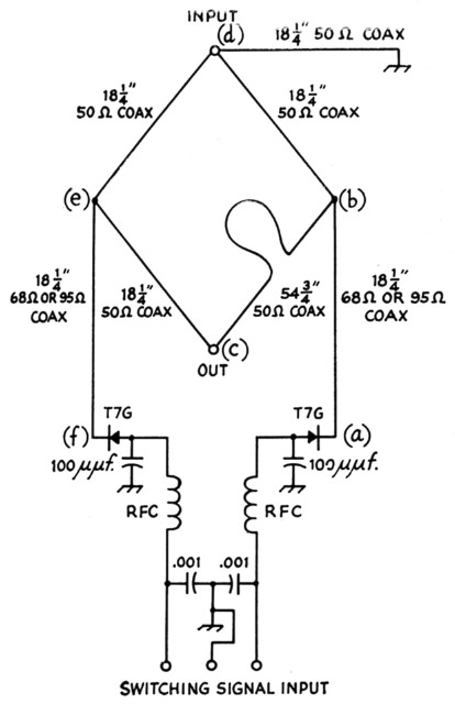
Fig. 8. Diode phase switch. RFC is self-resonant at 108 Mc.
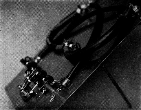
Fig. 9. Photograph of a phase switch similar to that shown in Fig. 8, but for higher frequency. Picture shows method of clamping coax to copper sheet near connector (upper right) and near diode (center). The plastic trimmer capacitor in the photo serves the same purpose as the 100 pF capacitor in Fig. 8.
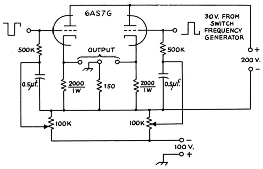
Fig. 10. Driver for diode phase switch. The bias on the 6AS7G triode sections is adjusted to cutoff by means of the 100K potentiometers, with no input from the switch-frequency generator. A push-pull square wave having a peak-to-peak amplitude of about 30 volts is needed for excitation of this circuit. D.c. coupling to the source is not required.
The operation of the switch can be understood if it is remembered that a short looks like an open when seen through a quarter-wave-length piece of transmission line. So when one of the diodes is conducting (for example, the diode at a in Fig. 8), it appears open as seen from b. Hence, the signal can pass from input to output along path dbc. The other diode is open and so appears as a short at e. This short in turn appears as an open at the input and output and does not interfere with the signal on the other side. When the switching signal changes over, the r.f. signal changes to path dec, which is a half wave length shorter.
The other unusual item is the phase-sensitive detector, or the device that tells us whether the source is near a maximum of the antenna pattern in Fig. 1A or of the pattern in 1B. This circuit, Fig. 11, can be seen to be a switch which turns the output of the receiver on and off in time with the phase switch. The reference signal to the phase detector, although derived from the same source as the switching signal, must be adjusted to have the correct phase. The narrow-band audio amplifier will have some phase shift and must be compensated for.
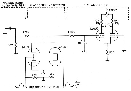
Fig. 11. Phase-sensitive detector and meter driver. Resistors are ½ watt. The reference signal (push-pull) should have a peak-to-peak amplitude of about 30 volts, and is taken from the switch-frequency generator. Its phase should be adjustable in order to compensate for phase shift in the receiver amplifier.
If an ordinary 0-1 mA recording meter is used, the d.c. amplifier in Fig. 11 is adequate.
A few hints
It can be seen from the above description that building an interferometer, although not requiring any unusual techniques or parts, is still a fairly large job. Probably the hardest part will not be finding or building the components, but in securing satisfactory operation from all of the components connected together. A few comments are then perhaps in order to try to smooth the path as much as possible.
Things work much better if they have stable supplies of plate voltage and filament voltage. Get out The Radio Amateur's Handbook and build a few regulated plate supplies. Invest in a Sola or other regulating transformer for the filaments. If at all possible, keep the receiver in a room in which the temperature does not vary widely.
When looking at radio stars the exact frequency does not matter, but for the satellite the receiver should be tuned to 108 Mc. within a kilocycle or so. This means that if you build the converter or mixer to go with the receiver, the oscillator must be crystal controlled. In order to be sure the receiver is tuned correctly, a 100 kc. frequency standard could be used to calibrate a stable v.f.o. at 27 Mc. The fourth harmonic of this oscillator can then be used to line up the receiver to 108 Mc.
Keep a speaker attached to the detected output of the i.f. amplifier. This is the easiest way to tell when you have interference problems, an oscillating preamp, or other troubles. When the receiver is working properly, the steady swish of noise should be heard. Dig out your July, 1953, copy of QST and build yourself a simple noise generator and use it frequently to check the noise figure of your preamp and the over-all behavior of your receiver.
Notes
- Record kindly supplied by Mr. H. W. Wells of the Carnegie Institution.
- Simas, "A low-noise preamplifier for satellite tracking," QST, Dec., 1956, p. 42.
John Firor.