Combination regulated power supply
Extending the range of regulated output voltage.
A nominally 250-volt regulator circuit is moved up by steps in the voltage spectrum through the device of increasing the stabilized reference voltage.
The power supply described in this article makes use of relatively inexpensive components and gives good voltage regulation from zero output to full load current and with varying input voltage. The output voltage is variable over a 1200-volt range with front panel control.
The circuit, Fig. 1, is a combination of two commonly used regulator circuits. The gas-filled regulator tubes are used to establish a fixed reference voltage, to which is added an electronically regulated variable voltage.
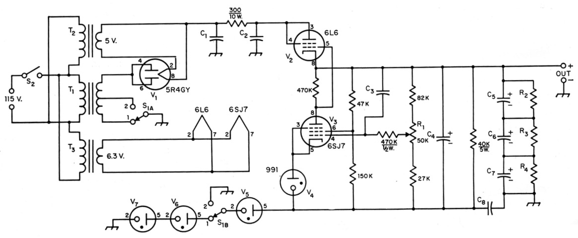
Fig. 1 - Circuit of the regulated power supply. Resistors are 1 watt unless indicated otherwise. See text for discussion of constants for various voltage ranges.
| C1,C2 | 4 µF paper, 1500 V. |
| C3 | 0.1 µF paper, 600 V. |
| C4 | 12 µF electrolytic, 450 V. |
| C5,C6,C7 | 120 µF electrolytic, 350 V. |
| C8 | 4 µF paper, 600 V. |
| R1 | 50 kΩ potentiometer, 1 watt or higher rating. |
| R2,R3,R4 | 27 kΩ, 2 W. |
| S1 | D.p.d.t. rotary. |
| S2 | S.p.s.t. toggle. |
| T1 | Power transformer, voltage and current ratings as required (see text). For output voltages of approximately 700 and 350, Merit type P-3175 (1100 volts center-tapped) is satisfactory. |
| T2 | Filament transformer, 5 V, 2 A. |
| T3 | Filament transformer, 6.3 V, 1.2 A (may be combined with T2 in a dual-secondary transformer). |
| V5 | 0A3/VR75 (see text). |
| V6,V7 | 0D3/VR150 (see text). |
In the author's transmitter the circuit is used with 4-125A tubes to provide regulated screen voltages of 350 volts for Class C operation when switch S1 is in Position 2, and 615 volts for Class AB1 operation when S1 is in Position 1. The power transformer is a surplus unit with 600 and 1000 volt taps, a combination which is not an ordinary catalog item, but the transformer suggested in Fig. 1 will give approximately the same voltages. The design can be modified to give any voltage from 225 volt to 1200 volt, with each voltage design center variable ± 60 volt. The maximum output current is determined by the power transformer, rectifier, and electronic regulator tubes.
The number of gas voltage-regulator tubes needed can be found by subtracting 250 volts from the wanted output voltage to get the approximate reference voltage, and then adjusting this reference to the nearest value obtainable from combinations of gas regulator tubes. For example, if the wanted output voltage is 350 volts the nominal reference voltage is 350 - 250 = 100 volt. Either a VR75 or VR105 can be used. A VR75 is used for this output voltage in Fig. 1 in order to reduce the power dissipation in the 6L6 regulator tube.
The 615-volt output was computed as follows: 615 - 250 = 365 VR150 + VR150 + VR75 = 375 volt. The necessary reference gas-regulator tubes can be calculated in the same way for voltages up to 1200 volt.
For output voltages higher than 615 volt, the transformer T1 will have to be changed. The voltage ratings of Cl and C2 also will have to be increased in proportion to the increase in output voltage. Additional capacitors and associated bleeder resistors will have to be added in series with C5, C6 and C7 so that the total voltage rating is greater than the output voltage. Also, the voltage rating of C8 has to be more than the total of the ignition-voltage ratings of the gas regulator tubes.
To increase the current-carrying capacity of this regulator two or more 6L6 tubes can be used in parallel. The current through each tube should not be over 90 mA. The current-carrying capacity of the transformer T1 has to be greater than the total current required from the output of the regulated power supply, of course.
The heater circuits of the 6L6 and 6SJ7 tubes should not be grounded. The heater winding should be insulated from the transformer core and should not break down with a voltage equal to the output voltage of the power supply.
With high voltage outputs it may be necessary to mount the voltage-control potentiometer with insulating washers on a bracket behind the panel and bring an insulated shaft through the front panel.
The rectified and filtered d.c. input voltage to the regulator should be a minimum of 50 volts higher than the required maximum output voltage.
L.D. Chipman, W4PRM.