A window sill antenna
80 through 6 with a small antenna system.
No place for an antenna? Not the conventional type, perhaps, but where there's a window there's a way.
This article describes a simple antenna system of small phsyical size for those amateurs who have no space for conventional antennas. We call it a "window-sill antenna" because it is intended particularly for those who live in apartment buildings or rented rooms and have access to a window but have no other antenna facilities.
One of its features is that it can quickly be put up or taken down, if necessary - a feature that should appeal to amateurs who have reluctant landlords! This is accomplished by using a collapsible whip antenna mounted on a small platform that can be hooked on a window sill. Details for one type of mounting, offered as a suggestion, are shown in Fig. 2; you may need something different for your location.
If the window you plan on using is at the second floor level or higher, the whip can be mounted either horizontally or vertically, but horizontal mounting is preferable because it has the advantage of getting the antenna farther away from the building. At ground level or the first floor, the antenna should be mounted at an angle of 45 degrees or vertically with its base two feet or more from the wall of the building.
The antenna can be used on any of the bands from 80 through 6 meters. This is made possible by using a combination loading coil and matching circuit for coax line, as shown in Fig. 1. When fully extended, the whip (Ward Model SC-8) is 100 inches long. This length, plus the two or three feet of wire needed to connect from the base of the whip to the coil, is very short for 80 or 40 meters, but on 20, 15, 10 and 6, the length is comparable with a quarter wave length.
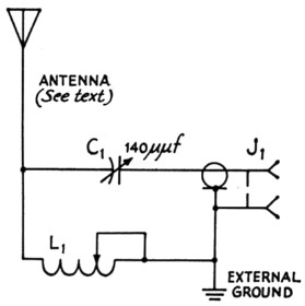
Fig. 1. Circuit diagram of antenna and coupling circuit.
| C1 | 140 pF variable (Hammarlund MC-140-S). |
| J1 | Coax chassis receptacle, 5O-239. |
| L1 | 24 turns of No. 12, 6 turns per inch, 3 inches diam. (Air-Dux 2406). |
Antennas that are extremely short for a given band, such as this one on 80 and 40, are not very efficient radiators. But when it is a choice between an inefficient system and no antenna at all, it's a case of anything is better than nothing. And after all, mobiles do operate with just such antennas - and manage to have satisfactory contacts with quite low power.
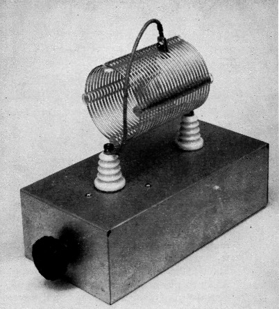
The coupling circuit is constructed on a 3 × 5 × 10 inch aluminum chassis. An eight-inch length of wire is connected to the grounded end of the coil. This, with the clip at its end, serves to short out the unused portion of the coil. The clip is an E. F. Johnson Type LC8.
On 20 meters and higher frequencies the antenna efficiency improves, and the principal handicap is that a window-sill location is not the best place that could be chosen for a radiating system. However, necessity governs when no other spot can be used.
The system described was tested on several bands at different locations. Here at Headquarters the building has a steel frame, typical of many apartment buildings so far as construction is concerned. The antenna was also tried at the home QTH of W1ICY, a two-story frame house. At both places the antenna was mounted horizontally at the second-floor level. Several contacts were made on each band from both locations. The power input was about 50 watt and the worst signal report received was a 5-6-9 from Illinois. (We won't list all the 5-9-9 reports, but we did receive a few!) One other installation was tried with the antenna mounted vertically a few feet above ground level. A three-foot metal stake driven into the ground was used for the ground connection. This setup more or less duplicates the average mobile installation. Several satisfactory contacts were made with it.
Coupling system
Construction of the loading coil and coupling system is simple. L1 is mounted on Johnson Type 135-46 feed-through insulators. The variable capacitor, C1, is mounted on a 2½ × 3 inch piece of Lucite. A small right-angle bracket, ½ × ½ × 3 inches, is used to hold the Lucite to the chassis. An insulated coupling is used in conjunction with a panel bearing and shaft to bring the capacitor control to the front of the chassis. This reduces any hand-capacitance effects when adjusting C1, if the ground lead is short.
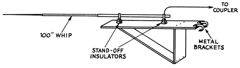
Fig. 2. This drawing shows one method of constructing a window mount. The metal brackets for hooking to the window sill can be made from shelf brackets available at any hardware store. The whip is supported by two steatite stand-off insulators.
Installation and Adjustment
The antenna preferably should be installed on a window that is near a heating radiator or water pipe. Either of these makes a reasonably good ground connection - in fact, any extensive metallic system such as water piping or the metal frame of a building will, generally speaking, be a better "ground" than a rod driven into the earth and connected to the coupling circuit through a wire of appreciable length.
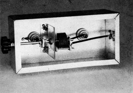
Bottom view of the coupling unit showing the method for mounting C1 on the Lucite bracket. An insulated shaft coupler is used to connect the rotor of C1 to the shaft for the tuning knob.
The simplest method of tuning is to use a standing-wave-ratio bridge in the coax line between the transmitter and coupler. If you don't have such a bridge then by all means build or buy one. Several different units are described in the measurements chapter of the Handbook.
Let's assume you're going to tune the system up on 40 meters. First, set your transmitter to the frequency you want to use in that band. Turn on the rig and set your s.w.r. bridge for reading reflected power. Tune C1 and see if there is any sign of a match, indicated by a reduction in the reflected-power reading. At first, you'll probably find that there is no such indication, unless you are lucky enough to have the coil tap at the correct position. Finding the right place for the tap is the problem. Move the tap up or down the coil and tune C1 again. Continue taking trial tap positions until you find one where tuning C1 causes the reflected-power reading to take a dip. Then move the tap a fraction of a turn at a time until you are able to bring the reflected-power reading down to zero with C1. It will usually rise rapidly as C1 is tuned on either side away from the correct setting, especially on the lower-frequency bands, because a small antenna system such as this will tune quite sharply. Once you find the proper tap point on the coil and the correct setting of C1 as indicated by a reflected current of zero, the antenna is tuned for that frequency.
The same tuning procedure is used for all bands from 80 through 15 meters but the tuning will tend to be less critical on the higher bands where the antenna is longer in terms of wave length.
It is a good idea to make up a chart showing the proper tap points for each band. This will save a lot of work when you change bands. The amount of coil you'll need will depend on the band. Most of the coil will be used for 80 meters and less and less as you go to the higher-frequency bands. On 10 you won't need any coil; on 6 the whip should be shortened to 55 inches which is approximately a quarter wave length on that band.
If you happen to live several floors above the ground there is a simple method of increasing the efficiency of the system on 80 and 40. You can lengthen the antenna by clipping a wire to the end of the whip and letting it hang down. How much wire you can use will depend on the height.
The author would appreciate hearing from anyone who manages to work all states using this system. After all, it isn't impossible!
Lewis G. McCoy, W1ICP.