Transistor regenerative detectors
A two-transistor receiver for 80 meters.
Those who like to experiment with transistors will find some useful tips here on using them as regenerative detectors. A complete receiver circuit is shown.
Transistorizing of short-wave communications equipment is worthy of serious consideration. The advantages in size, weight and efficiency are well known. Considerable progress has been made with transistorized transmitters, and although power is still in the "flea" category, many an operator of a healthy fraction of a kilowatt can recall an earlier era of amateur radio when global contacts were fairly common with ten watts or less. As a rule, transistor transmitters generate less than one watt, but even this is practical for communication over respectable distances.
In the case of the receiver, cost becomes a discouraging factor if a transistor superheterodyne is contemplated. The regenerative circuit has probably been considerably experimented with, but in the author's experience it is not always easy to get good results from a regenerative circuit even in the broadcast band - and for a time it appeared that any results at all at high frequencies could be considered an accomplishment! Notwithstanding this somewhat pessimistic philosophy, the set to be described outperforms a two-tube version of the same circuit in several ways. It is more stable, less noisy, and is smoother to operate than a tube set. Its sensitivity is every bit as good as that of its tube counterpart.
Before discussing the actual circuit, it would be well to consider a certain peculiarity of transistors. The current gain factor, β, of a transistor connected in the grounded-emitter configuration, is roughly analagous to the voltage amplification factor, µ, of the vacuum tube. However, the β of a given type of transistor can vary more from transistor to transistor than a does for a range of three types of tubes such as the 12AU7, 12AT7, and 12AX7. In addition, the β cut-off frequency often varies as much as *50 per cent among individual transistors of the same type designation. Because of this, a minimum β and a minimum β cut-off frequency are required for the detector transistor. This does not imply that the circuit is tricky but is an expected manifestation of the very loose tolerances which exist in designated type numbers of transistors.
The circuit is designed to operate in the 80-meter phone and c.w. band. The detector transistor does not have to have a β cut-off frequency in the vicinity of four megacycles, as might first be supposed, because the detector does not behave as an amplifier at radio frequencies. Rather, the r.f. is demodulated by the emitter-base diode, in which the β cut-off mechanism does not operate. The collector-base diode amplifies audio frequencies (which are far below β cutoff) and must, in addition, provide a small amount of radio-frequency energy for regeneration. Thus, some consideration must be given to β cutoff but the demand is relaxed considerably as compared with the cut-off frequency which would be required if the transistor operated primarily as a radio-frequency amplifier.
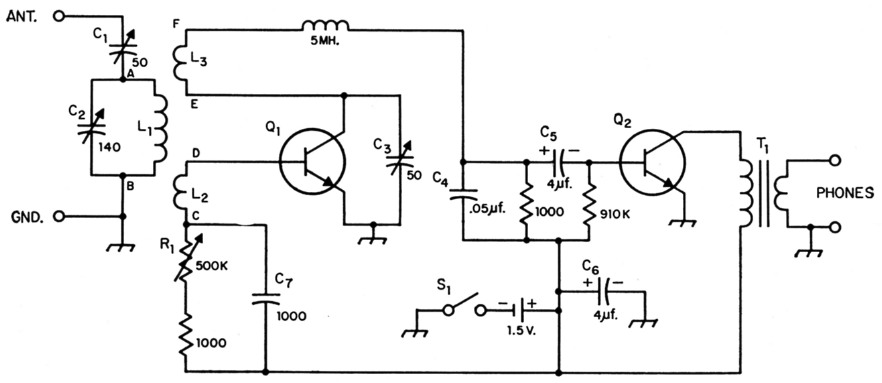
Fig. 1. Circuit of the transistor regenerative receiver. Unless otherwise indicated, capacitances are in pF, resistances are in ohm, resistors are ½ watt.
| C1 | 50 pF variable, ceramic or air trimmer. |
| C2 | 140 pF variable (tuning). |
| C3 | 50 pF variable (regeneration). |
| C4 | Paper or ceramic. |
| C5,C6 | Electrolytic; tantalum type for miniaturization. |
| C7 | Mica. |
| L1,L2,L3 | See Fig. 2. |
| Q1,Q2 | NPN transistor (see text). |
| R1 | 500 kΩ potentiometer (regeneration). |
| S1 | S.p.s.t. toggle. |
| T1 | Audio transformer, 3 to 1 ratio, step down to headset. |
As shown in Fig. 1, the detector bears a close resemblance to a grid-leak tube circuit. The 5 mH r.f. choke in the collector circuit is an absolute necessity, inasmuch as it extends the frequency limit at which the detector is able to regenerate. This choke should not be bypassed at the point where it connects to L3, as normally would he the case, but should be connected as shown in the circuit diagram.
The incoming high-frequency energy must be stepped down in impedance, through L1L2, because the input impedance of the emitter-base diode is too low for connecting directly across a tuned circuit.
Two regeneration controls are provided, to make the receiver flexible with respect to different transistors. Once satisfactory operation is achieved with a given transistor, either R1 or C3 may be made fixed. Regeneration is increased by decreasing the value of C3 or decreasing the value of R1.
The audio amplifier is a conventional grounded-emitter stage. β cut-off frequency need not be considered here, but the higher the β of this transistor, the greater the audio amplification. T1 is connected as a step-down transformer to bring about an approximate match to the headphones.
The entire receiver can be powered from a single penlight cell. The total current drain is approximately 1.5 mA. An antenna consisting of twenty feet of wire provides excellent reception. Of course, the antenna requirements can be expected to vary with location and environmental conditions. In the author's model, a ground was found helpful in reducing hand capacity. A vernier tuning dial is desirable, and a small variable capacitor across C2 would be useful for band-spread tuning.
The coil winding data are given in Fig. 2. The specifications should be followed as closely as possible. Do not substitute different wire sizes or alter the physical relationships of the three coils. It is very important that the coil connections be made as depicted in Figs. 1 and 2. If a plug-in form is used, the manner in which the coils are connected to the pins is not of great importance; this is left to the discretion of the constructor.
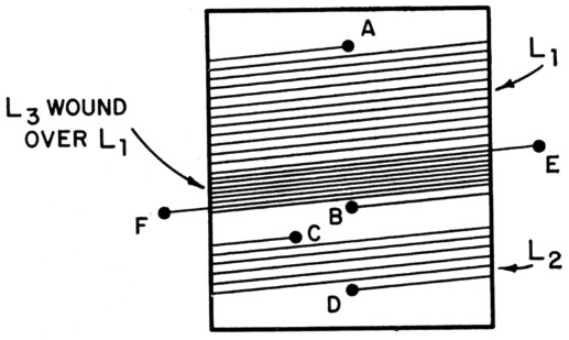
Fig. 2. Coil construction. All three windings are on a 1¼ inch diam. form (octal tube base). All coils are close-wound. For convenience in inserting the identifying letters in the drawing above, a small space is shown between L1 and L2 but the coils should be wound with no space between them. L3 is wound over the bottom end of L1. L1 has 19 turns of No. 31 enam. wire; L2 and L3 each have 8 turns of No. 27 d.c.c. wire.
The transistors are intended to be General Electric type 2N78 NPN germanium units, or the type ZJ6-18 or ZJ6-32 (also made by General Electric). Any of these three types will be satisfactory for the detector transistor, Q1, providing β is at least 60 and the cut-off frequency is no less than 200 kilocycles. This requirement can be met by any of these three types. However, not all 2X78s or ZJ6-18s will measure up to specifications. If the supplier is not willing to select one of these transistors for the specified parameters, it is better to order the type ZJ6-32. The β cut-off frequency of the ZJ6-32 may run well over 300 kc. This is not always accompanied by βs of 60 or higher but in this case the high cut-off frequency relaxes the requirement for β. The net result is that the receiver may be expected to work with any ZJ6-32 and with selected 2N78s or ZJ6-18s.
Any of the three transistor types mentioned will be satisfactory for Q2, the audio stage. The β cut-off frequency is of no consequence here. Of course, the higher the β the more audio amplification will be provided. βs of 30 or so are entirely satisfactory and really "hot" performance is provided by transistors with βs in the vicinity of 60.
It may be more convenient to specify the a rather than the β parameters when ordering. For this purpose, the following relationships are useful:
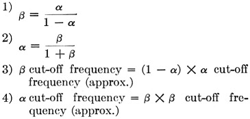
where β is defined as the current gain in the grounded-emitter configuration when the load impedance is zero, a is defined as the current gain in the grounded-base configuration when the load impedance is zero, and β or a cut-off frequency is the frequency at which the output has decreased 3 db. with respect to a low audio frequency, say 1000 c.p.s. β cut-off pertains to the grounded-emitter circuit and a cutoff is used in connection with the grounded-base circuit, both with zero load impedance.
Irving Gottlieb, W6HDM.