An ultrastable keyed V.F.O.
Remotely tuned unit with good c.w. performance.
This article describes a v.f.o. of better than average stability. Chirps and clicks are virtually eliminated by operating the tube just within the threshold of oscillation and reducing the voltage change with keying to the minimum value that will provide reliable control of oscillation. Attention to detail results in a unit that also has exceptional freedom from drift.
From the theory of inductance-capacitance oscillators it is evident that the effective Q of the tuned circuit is a primary factor in determining stability. However, in order for the theory to have practical significance, assumptions have to be made that the values of inductance and capacitance in the tuned circuit remain absolutely constant.
What usually happens in practice is that the effective Q of the tuned circuit is drastically lowered by the time it is serving in an oscillator circuit, and that the inductance and capacitance do not stay constant. From this it might be inferred that most practical forms of v.f.o.'s are not as stable as they could be. That conclusion can be verified by some careful listening at low beat frequencies. Rare indeed is a v.f.o.-controlled signal found on 14 Mc. or higher that drifts only an imperceptible amount when first turned on or when keyed.
Such a signal is generated by the v.f.o. to be described. Its frequency stability performance is summarized by Fig. 1, where it is compared with one of the commercially available v.f.o.'s, each operating for more than an hour from a cold start. Drift of the commercial v.f.o. is 63 parts per million as compared with 2 parts per million for the ultrastable one. Driving a buffer followed by three doublers and a 150-watt final amplifier, the frequency of the ultrastable v.f.o. changes three cycles or less from that running alone. Keying by a rather unique method in the screen-grid circuit, the keying is cliekless, chirpless and about as nearly perfect as the word can be defined.
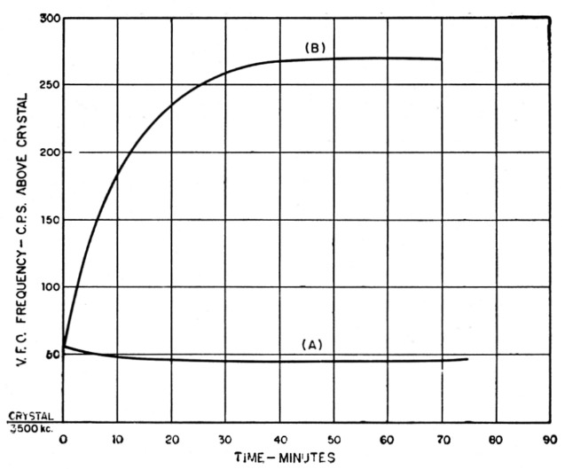
Fig. 1. Relative frequency drift of the ultrastable v.f.o. (A) vs. a commercially-available unit (B).
All this was obtained by putting stability ahead of all other considerations in the design of a practical v.f.o. The design details can be summed up in two basic rules:
- Use a tuned circuit with as high Q as possible, and then don't lower this Q any more than absolutely necessary for the maintenance of oscillations.
- Give the inductance and capacitance in the tuned circuit a chance to remain absolutely constant, at least to the extent possible without resorting to temperature control.
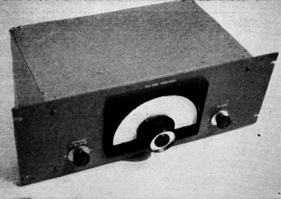
The rack panel of the tuning unit is 7 inches high. The controls on either side of the dial are for the bandsetting capacitors.
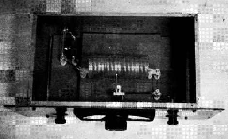
The tuning unit of the ultrastable v.f.o. is enclosed in a 7 × 9 × 15 inch aluminum box to minimize the reduction in coil Q by the shielding. The two feed-back capacitors are in the upper left-hand corner.
Keying
Before discussing the features and construction of the ultrastable oscillator, a few more remarks about how it keys: With due regard for many unsatisfactory results, the Handbook tends to shy one away from keying a v.f.o., saying in effect that in the effort to compromise between clicks and chirps, "perfect" keying is a virtual impossibility particularly at 14 Mc. and higher frequencies. What happens with this v.f.o. is that be cause it operates near the threshold of oscillation, and because of the small voltage change with keying, it keys without the least sign of a chirp or click when driving two 5763 doublers and a pair of 807s in the final amplifier. And "without the least sign" refers to a check for transients with an oscilloscope as well as a listening check. Such results are not so surprising if you consider that the voltage across the key when up is only of the order of two volts. But this is getting ahead of the story. More will be told about the keying system in the description to follow.
Circuit
Since the series-tuned oscillator was introduced by J. K. Clapp(1) it has become something of a standard circuit for v.f.o.'s. Despite some controversy over its relative advantages and disadvantages for a stable oscillator, its advantages appear to outweigh its disadvantages for two reasons, neither of which is that it is inherently or theoretically more stable than other inductance-capacitance oscillator circuits. The first reason is that it enables practical realization of a higher effective tuned-circuit Q than most other circuits.(2) The second is that it is inherently well suited for physical separation of the tuned circuit from the tube circuit portion. This physical separation is of utmost importance in carrying out Rule 2 above. As little a temperature change as 2 degrees Fahrenheit has a perceptible effect on frequency, and heat from a tube adjacent to a tuned circuit must be avoided if stability is the first consideration.
This v.f.o. uses the series-tuned circuit and is divided into two separate sections - the tuned-circuit portion and the tube portion. The tuned-circuit portion is illustrated by the first and second photographs and is diagrammed in Fig. 2.
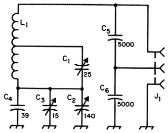
Fig. 2 - Circuit of the remote tuning unit.
| C1 | 7-25 pF variable (Bud CE-2001 with 2 plates removed should be satisfactory(3). |
| C2 | 140 pF variable (Hammarlund HF-140). |
| C3 | 15 pF variable (Hammarlund HF-15). |
| C4 | 39 pF silver mica. |
| C5,C6 | 0.005 µF silver mica. |
| J1 | Twin receptacle (SP-264). |
| L1 | 45 µH - 44 turns No. 14, 2½ inch diam., 5½ inches long, center-tapped (B & W 3906-1 or Airdux 2008). |
There are two significant differences between this tuned circuit and that of most Clapp v.f.o.s which have been described previously. One is that the tube coupling capacitors are .005 µF instead of the .001 µF frequently used. The second is that the main tuning capacitor is isolated from ground by an insulated shaft and tapped across a portion of the coil. The first of these features decreases the coupling between tuned circuit and tube by a factor of 25, and increases the theoretically possible stability by a factor of five. The tube used must of course have enough mutual conductance to sustain oscillations under this condition. The second feature serves two useful purposes: (1) the tap, made with heavy solid wire at the top of the coil, adds to the rigidity of the coil assembly, and (2) any desired degree of band spread can be had by selection of the tap position.
Tuned-circuit enclosure
Designed to cover a frequency range of 1.6 to 2.0 megacycles, the tuned-circuit assembly has traded space for stability in that the 7-inch high by 9 inch deep by 15 inch wide aluminum box (Premier AC-1597) is none too large to house the 2½ inch diameter, 5½ inch long coil. A smaller coil or smaller box or both would have lowered the Q. The coil and box used represent an all out effort to obtain maximum tuned-circuit Q within dimensional limits of a standard rack. The lower box cover was reinforced with 34-inchthick plywood before mounting a 1 inch thick plywood base which supports the coil on stand-off insulators to the center height of the box. The original top box cover was replaced with a Minch-thick aluminum cover to increase rigidity.
Tuned-circuit constructional details
As shown in the photo looking down into the tuned-circuit box, all connecting leads are made with No. 12 solid wire, and the lengths are broken up by stand-off insulators so that no length remains unsupported more than about 3 inches. This kind of lead rigidity, plus rubber feet on the bottom of the box, minimizes twang from bump ing or pounding on the operating table.
A length of RG-22/U cable terminated at each end by a PL-284 plug couples the tuned-circuit box to the tube portion of the v.f.o. This cable assembly is a critical point at which the stability of the v.f.o. can be ruined if the terminations are not good. A poor soldering job at either plug, or any relative motion between plug and cable, can cause frequency variations which might not be noticed in an ordinary v.f.o. but which look monstrous when you are checking stability down to the last cycle.
There has been considerable discussion in articles describing v.f.o.'s about the necessity for excellent contact in the tuning-capacitor bearings. The tuning capacitor used in this v.f.o. has a flexible pigtail between the rotor and the rotor-connecting terminal, thus eliminating completely any possibility of trouble at this point. If one like this cannot be obtained commercially, it is possible to drill and tap the back end of the shaft of a standard type and attach a pigtail with a small screw.(3) Since the rotor of the tuning capacitor should not be grounded, an insulating shaft extension must be used.
With the coil tap at the position indicated in Fig. 2, the range of the tuning capacitor is 1750 to 1775 kc. over 95 degrees, which is an excellent band-spread rate for the 14-Mc. band. With the tap on the 14th turn from the grid end of the coil, the range is 1750 to 1800 kc.
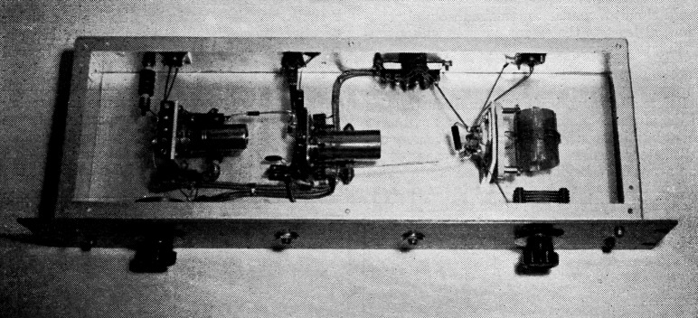
The v.f.o. tube and buffer-doubler are housed in a 6 × 17 × 3 inch aluminum chassis behind a 3½ inch rack panel. The potentiometer at the left is for adjusting the keying threshold. The doubler tank circuit is to the right.
Tube Portion
As shown in the third photograph, the tube portion is assembled in a 6 × 17 × 3-inch aluminum box attached to a 3 × 19 inch panel for rack mounting. The circuit diagram is shown in Fig. 3. With the entire unit operated from a 150 volt regulated power supply, ample output is obtained from the second half of the 12AV7 at 3.5 Mc. to drive a 5763 doubler. Neutralization of the buffer is not required because of the un-tuned grid and plate circuits.
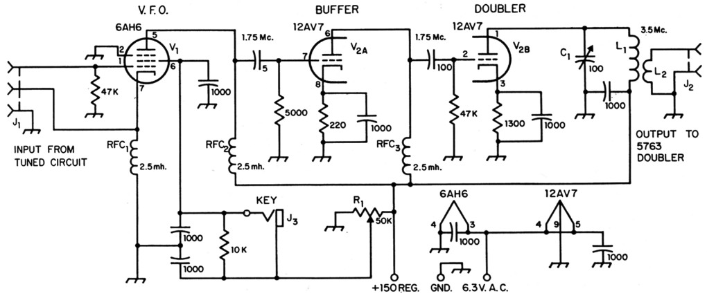
Fig. 3. Circuit of the tube section. All capacitances are in pF. All 1000 pF capacitors are disk ceramic. Coupling capacitors are mica or ceramic. All fixed resistors are ½ watt. All RFCs are standard 2.5 mH r.f. chokes.
| C1 | 100 pF variable, receiving type. |
| J1 | Twin receptacle (SO-264). |
| J2 | Coax receptacle (SO-239). |
| J3 | Open-circuit key jack. |
| L1-L3 | 40 µH - 50 turns No. 22, 1¼ inch diam., 2 inches long; 3 turn link (B & W MEL-80). |
The oscillator circuit is straightforward except for the keying system and the very loose coupling to the grid of the 12AV7 buffer by only 5 µµf. of capacitance. The 50K potentiometer in the oscillator screen circuit serves as a threshold control and is normally adjusted so that with the key down the oscillator is just within the threshold of oscillation and gives just enough output to drive the first half of the 12AV7 as a Class A amplifier without any grid current. The output of the first half drives the second half as a doubler to 3.5 Mc.
With the key up, the 10K resistance across the key drops the screen voltage about 2 volts, which throws the 6A116 tube out of oscillation. This inherent switching action by a change of only 2 screen-grid volts occurs in the oscillator only when it is operating just within the threshold value of screen-grid voltage to sustain oscillations. Once that operating value is set, the 2-volt change by keying turns the oscillator on and off without the least chirp or click. Moreover, key-up and key-down heating effects are practically identical, thereby further reducing the possibility of drift caused by changes in tube capacitances.
At the 1.75 Mc. point in the tuning range, the critical screen-grid voltage for oscillation is 61 volts. With 60 volts on the screen the circuit is dead and with 62 volts it oscillates with just enough power to drive all the following stages to full output. The first half of the 12AV7 amplifier operates as a true Class A amplifier, and does not draw any grid current until the oscillator screen voltage is raised to 70 volts. For a two-volt keying difference across the 10K resistance, it is necessary to adjust the threshold control slightly for about each 50 kc. change in fundamental frequency. If this is considered an operating disadvantage, as it may be on the low-frequency bands, the resistance across the key can be increased so as to allow keying control of oscillation over an entire band with the threshold control set just within the threshold of oscillation at the highest frequency. For example, at 2 Mc. the threshold voltage is 81. With the control set for 82 volts key down and 100K ohms across the key, the screen voltage is 60 with the key up and the full range of 1.75 to 2 Mc. can be covered without adjustment. However, this condition is not optimum for stability except at 2 Mc., and the keyed voltage is more than the minimum necessary to control oscillation.
The very low coupling capacitance and low value of grid resistance in the grid circuit of the first half of the 12AV7 make the oscillator tube highly insensitive to anything that happens following it. With all following stages turned on, the frequency is at most 3 cycles higher than with the oscillator running alone. As compared with the click, chirp and shifting-under-load problems when trying to key an ordinary v.f.o. in the cathode circuit, this small difference represents rather superb performance for a keyed v.f.o.
Method of checking frequency stability
Fig. 4 shows a block diagram of the equipment used in making accurate tests of frequency stability. When an accurately-calibrated audio oscillator is used it is possible to measure a change of one cycle per second by this method. The audio oscillator used in this setup was a Hewlett Packard Type 200AB. Audio oscillators which have beat effects at 60 and 120 cycles may be used in this manner if one keeps away from the frequencies where these effects occur.
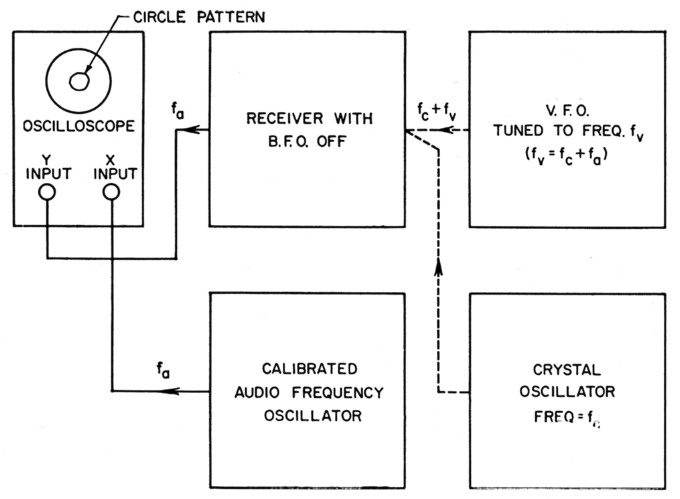
Fig. 4. Block diagram showing the method of checking v.f.o. frequency stability.
To make measurements, the v.f.o. is tuned to a convenient frequency 50 or 60 cycles higher than the crystal-oscillator frequency, picking up the beat ftequency fa from the receiver, and applying it to one set of plates of an oscilloscope. The output of the calibrated a.f. oscillator is applied to the other set of plates of the oscilloscope, and the a.f. oscillator is then tuned for a circle pattern. The a.f. oscillator dial then indicates the number of cycles per second the v.f.o. frequency is higher than the crystal oscillator. Beat frequencies below 100 cycles should be used to take full advantage of the a.f. oscillator calibration. The lower the beat frequency the better the accuracy, but frequencies below 40 cycles may not be passed by the receiver.
Additional test results
Fig. 5 shows the results of a test where the room temperature during the time the oscillator was on was increased to determine the approximate effect of change in room temperature on frequency. A thermometer was held near the tuned circuit box while the heating system of the room was on continuously for two hours and raised the temperature from 71 degrees to 73 degrees Fahrenheit. Setting the beat frequency at 60 cycles on a cold start, the frequency was 65 at the end of two bouts with the higher room temperature, indicating a temperature coefficient of frequency of about 0.7 part per million per degree Fahrenheit.
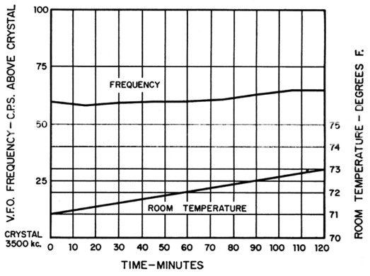
Fig. 5. Graph showing v.f.o. frequency change with change in room temperature.
Curve A in Fig. is an expanded plot of the frequency test shown in Fig. 5, which is the frequency of the oscillator alone with all the following stages off. Curve B shows the oscillator frequency with all following stages turned on. The maximum difference between the two on any measurement was 3 cycles per second and the average about 2. These data are rather convincing evidence that the oscillator is for all practical purposes unaffected by loading insofar as frequency stability is concerned.
A "perfect" keyed signal is one completely free of backwave, drift, chirps and clicks. When such a signal is heard it is usually assumed that a crystal is used or that the oscillator is not keyed. Here is how the ultrastable v.f.o. stacks up against these requirements:
There is no backwave since the oscillator is actually switched on and off by the small change in screen voltage. At constant room temperature, drift is not over 2 parts per million from a cold start, as shown in Fig. 1A. Chirps, as indicated both by listening and by oscilloscope check, using the setup of Fig. 4 are virtually nonexistent (less than one part per million). Without any waveform shaping circuit at the key, clicks tested by sweeping the receiver through and beyond the a.f. beat-frequency range as described in the A.R.R.L. Handbook are also virtually nonexistent. Reports from local stations, one only a block away, have confirmed the absence of clicks. A shaping circuit consisting of a 3 H choke in series and a 0.25 µF capacitor in parallel with the key showed no perceptible improvement in the character of the keyed signal, but it is interesting to note that the shaping circuit did not magnify the chirp as it usually does in conventional keyed oscillators. It should be remembered that the precautions mentioned in the Handbook in regard to the biasing of later stages in the transmitter must be observed to avoid introducing clicks in these later stages.
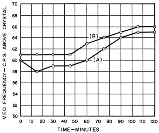
Fig. 6. Frequency drift (A) of oscillator alone, and (B) with entire transmitter on. The difference between the two curves represents the change in frequency when stages following the oscillator are turned on.
Notes
- Clapp, "An inductance-capacitance oscillator of unusual frequency stability," Proc. IRE, March, 1948.
- Edson, Vacuum tube oscillators, John Wiley & Sons, New York, 1953.
- This trouble has been avoided in some earlier v.f.o. designs (see QST for December 1948) by using a split-stator capacitor, the two connections being made to the stator sections with no connections to the rotor. The bearings are thus eliminated from the circuit. In this particular case, the capacitor should have 50 50. per section since the two sections are in series. - Ed.
J.M. Shulman, W6EBY.