Improved A.V.C. for side band and c.w.
Audio rectification and its advantages.
The requirements of a good a.v.c. system for side band and c.w. are a fast "attack" and a slow decay. Merely using a long time constant in the conventional a.v.c. circuit is not adequate. The hang a.v.c. system described early this year in QST was a step toward better a.v.c. for side band and c.w., and in this article WOBFL tells how he modified the basic circuit to give superior a.v.c. action; the circuit is readily applicable to many receivers.
Having acquired a Collins mechanical filter, I set out to build an i.f. strip around it, somewhat along the lines of the high-frequency i.f. amplifier described in QST.(1) The "hang a.v.c."(2) seemed like a good idea, but I remembered that Luther Couillard, of Collins Radio, writing in the December, 1956, issue of the I.R.E. Proceedings, suggested that receivers for side band and c.w. should derive their a.g.c. voltage from the audio, which would eliminate isolation problems and give extra gain for a flatter a.v.c. characteristic. As a consequence I revised the hang a.v.c. circuit for audio rectification and installed it in the new i.f. strip. It works so well that I want to pass it along to the rest of the side-band (and c.w.) gang. I've never seen a flatter a.v.c. characteristic on any receiver, there is no problem with b.f.o. leakage into the rectifier as there is with the i.f. type, and it is very simple to set the threshold of compression so that a product detector can be run at the level that is the compromise between detector overload and available audio gain.
Those familiar with the i.f. hang-a.v.c. circuit will see that the audio-a.v.c. circuit, shown in Fig. 1, bears a family resemblance. Audio from the receiver is amplified in the a.v.c. amplifier, and rectified in the attack diode. The resultant voltage is applied to the a.v.c. line through the attack gate diode. The capacitor C1 charges quickly and will remain charged until discharged by the recovery gate VLB. This will occur some time after the signal has disappeared, because the audio was stepped up through T1 and rectified in the recovery diode, and the resultant used to charge C2. This voltage holds V1B cut off for an appreciable time, until C2 discharges through the 4.7 megohm resistor.
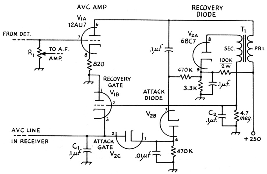
Fig. 1. Schematic diagram of the improved hang a.v.c. system. Resistors are ½ watt unless specified otherwise.
| R1 | Normal audio volume control in receiver. |
| T1 | 1:3 step-up audio transformer (Stancor A-53 or equiv.) |
| The hang time can be adjusted by changing the value of the recovery diode load resistor (4.7 megohms shown here). The a.v.c. line in the receiver must have no d.c. return to ground and the receiver should have good skirt selectivity for maximum effectiveness of the system. | |
A point of difference between this and the i.f.-type circuit, other than the frequencies involved, is the use of bias on both the recovery diode and the attack diode. If bias is applied only to the attack diode, noise and such can keep the recovery gate biased to cut-off and the a.v.c. bus won't discharge. The threshold of compression is set by adjusting the bias on the diodes (changing the value of the 3.3K or 100K resistors).
Before I tried the circuit, I wondered if the attack would be as rapid as with the i.f. type, but it appears to be instantaneous. Once in a while I get a strong noise pulse that will cause the a.v.c. to hang until C2 discharges, but most of the time the gain returns very rapidly to that set by the signal. For an S-meter circuit I use a triode and a 0-1 milliammeter in the conventional bridge, as shown in The Radio Amateur's Handbook. It holds so still on a steady s.s.b. or c.w. signal that you would think the meter was stuck.
I have spent considerable time and thought trying to improve the circuit still more, but it works so well for me now that I can't find a way to make it better. Possible improvements might be a self-adjusting noise clipper to prevent noise pulses from disabling the a.v.c., although this happens only rarely, as mentioned above. Some users might prefer to bypass the cathode resistor of the a.v.c. amplifier with a large electrolytic capacitor, to increase the gain of that stage. This necessitates raising the threshold bias if the audio output of the detector is to remain the same level as before. The additional gain should give a still flatter a.v.c. action, but I can notice no practical difference.
In my i.f. strip I feed manual gain-control bias to the a.v.c. bus through a diode and it works fine that way, but the a.v.c. works so well even on weak signals that I never use manual gain control.
Notes
- Goodman, "What's wrong with our present receivers?" QST, January, 1957.
- Goodman, "Better a.v.c. for s.s.b. and code reception," QST, January, 1957.
George W. Luick, WOBFL.