Compact AB1 Kilowatt
Single-tube amplifier runs 1000 watts input on s.s.b., c.w. or a.m. as a linear amplifier with no grid current. A new high power tube designed specifically for AB1 operation makes it possible.
Because it is the almost universal practice to generate an s.s.b. signal at a low level and then amplify it to the required output with one or more linear amplifiers operating Class A, AB1, AB2 or B, the linearity of the amplifying stages is all important. The stages following the best s.s.b. generator can turn a clean signal into one which is distorted and unnecessarily broad. Thus the need for truly linear amplifiers.
While the individual designer has his choice as to the class of operation in which the amplifier will run, Class AB1 has several desirable characteristics. Because the control grid is never driven positive the very serious problem of adequate driver regulation never has to be faced, as it does if the mode of operation is AB2 or Class B. In addition, no driving power is required for the tube: only the grid circuit losses must be supplied.
It should be pointed out that most tetrodes and many triodes appear as a resistance of 200 to 500 ohms from grid to cathode when the grid is positive. During the part of the r.f. cycle when the grid is negative the resistance is infinite. A driving source that can supply either an infinite resistance or a load of a few hundred ohms, with out distortion of the voltage wave form in either case, would have to have very low internal resistance. A working approximation is usually achieved by making the tuned grid circuits of r.f. amplifiers extremely high C. In audio amplifiers it is obtained by using low-plate-resistance driver tubes plus a step-down transformer.
Class AB1 amplifiers compare very favorably in efficiency with AB2 and Class B. In fact, overall amplifier efficiencies, which take into account the losses in the tube and the circuit, are usually of the order of 55 to 65 per cent. It is only when compared with Class C operation that AB1 represents a significant lowering of efficiency.
It is for this reason that some of the older tube types do not look particularly attractive in s.s.b. service. In the past almost all transmitting types were designed for optimum service in Class C amplifiers. This optimum provided a balance between plate current and plate dissipation; the higher efficiency realized required less plate dissipation capability for a given input power. In contrast, a tube designed especially for AB1 application would be expected, for a given output, to have a higher plate-dissipation rating than we have become accustomed to.
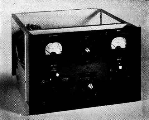
There is a pleasing symmetry to the control layout on the 10 × 15½ inch panel. The grid circuit is untuned, so the only r.f. controls are the band switch, plate tuning, and loading. Separate meters are provided for plate and screen currents, with the screen meter also used as a grid-current monitor. The amplifier, 15 inches deep, contains filament transformer and cooling fan in addition to the r.f. circuits.
The 4CX1000A Tetrode
A tube designed to have exceptionally good linearity in Class AB1 r.f. amplifiers is the newly announced Eimac 4CX1000A. It is a power tetrode of all ceramic and metal construction having an external anode capable of dissipating 1000 watts with 35 cubic feet of air per minute blown through the cooling fins. The filament requires 6.0 volts at 12.5 amperes to heat the oxide coated cathode. With the usual tetrode connection having the cathode and screen at r.f. ground, the grid-to-cathode capacitance is 85 pF, plateto-ground is 12 pF, and grid-to-plate is 0.02 pF. In spite of the low feed-back capacitance, the very high transconductance of 37,000 micromhos makes neutralization necessary if a tuned grid circuit is used. The maximum ratings are: plate voltage, 3000; plate current. 1 ampere; screen dissipation, 12 watts; control grid dissipation, zero watts.
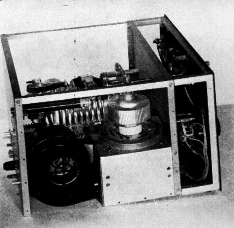
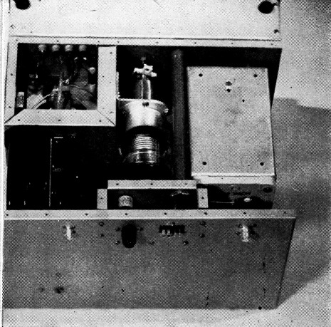
Vertical chassis construction is used, as this view from the tube side shows. The air-system socket is mounted on the 6 by 6 inch top of an aluminum enclosure 4 inches high, with the chassis pan forming one wall. When the bottom plate is in place this forms a pressurized area for forcing air from the blower through the socket. The socket chimney has been removed in this photograph to show the 4CX1000A tube.
The power output will vary with the type of service for which the tube is used. For single side band suppressed carrier single tone, the output is 1680 watts for 2700 watts input at the maximum plate voltage of 3000. If the driving signal is an amplitude-modulated carrier, either single or double side band, a carrier output of about 300 watts can be expected from a kilowatt input. If a c.w. signal is being amplified then the output power would be approximately 600 watts. Since for a.m. phone or for c.w. the carrier or key-down conditions apply in measuring power input, it is the legal power-input limit that largely determines the output power. In commercial service the capability is considerably greater.
The connection to each element is made by means of three metal tabs or ears which protrude through the side of the envelope at 120 degree intervals around the circumference. The screen tabs are nearest the anode; the control grid, cathode plus one side of the heater, and heater follow in order to the bottom. Ham ingenuity will make it possible for some to build their own sockets but most will use the Eimac SK-800 which has a built-in screen by-pass capacitor. The height of the tube is just under 4¾ inches, and the diameter approximately 3_3/8 inches.
The use of ceramics instead of the usual glass for the envelope makes the 4CX1000A much more rugged mechanically and makes possible a higher operating temperature. The first feature is very handy for the time the prized bottle rolls off the table onto the floor!
It will be noted above that the control grid is rated at zero dissipation. In designing the tube for AB1 operation the location and number of grid wires was not hampered by compromises such as would be necessary if the grid were called upon to handle power. Consequently, a large number of fine wires were closely spaced to the cathode to give an unusually sharp-cutoff grid voltage-plate current characteristic. Thus linearity is maintained near cutoff.
While the tube is capable of powers in excess of the legal amateur limit it is quite legal to have peak inputs in amateur service well in excess of a kilowatt if the average power does not exceed that figure. (If there are doubters, please read the excellent article by Byron Goodman, " Linear Amplifiers and Power Ratings," in August 1957 QST.) In such cases the tube cathode is asked to supply quite high currents and must be capable of such operation if linearity is to be maintained.
A Compact Amplifier
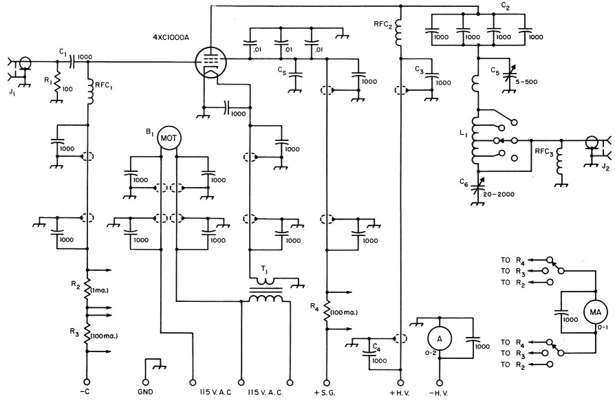
Fig. 1. Circuit diagram of the amplifier. Unless otherwise indicated, capacitances are in pF, resistances are in ohms. Capacitors not listed below are 600 volt disk ceramic. B1 Blower motor.
Note: Power lead for blower motor is brought out separately for resistance control of speed during stand-by.
| C1 | 1000 pF mica. |
| C2 | Four 1000 pF ceramic in parallel, 5000 volt rating (Centralab 858). |
| C3,C4 | 1000 pF ceramic, 5000 volt (Centralab 858). |
| C5 | 5-500 pF vacuum variable (Jennings UCSL 500 3 kV). |
| C6 | 20-2000 pF vacuum variable (Jennings UCSL 2000 2 kV). |
| C6 | Built-in socket bypass, 1450 pF. |
| J1,J2 | Coax receptacles, chassis mounting. |
| L1 | Pi-network tank assembly (B & W 852). |
| R1 | 100 ohms, noninductive, to dissipate at least 15 watts (see text). Can be assembled from 2-watt composition resistors in parallel or series-parallel. |
| R2 | Approx. 1000 ohms (should be 20 or more times meter resistance). |
| R3,R4 | Adjusted to shunt 1 mA meter for 100 mA full scale; approx. 0.5 ohm in average case. |
| RFC1,RFC3 | 2.5 mH r.f. choke. |
| RFC2 | Solenoid choke, 500 mA (B & W 800). |
| T1 | Two 6.3 V, 6 A transformers parallelled. |
The tube is a relative midget in size and the challenge to design a small amplifier of high power capability could not be resisted. So the amplifier shown in the photos, contained in a package measuring 10 inches high by 15 inches wide by 15 inches deep, came into being. The r.f.-tight enclosure is 12 inches front to back, with a 3-inch space between the front panel and shielded box. Not shown in the photographs are the perforated aluminum U-shaped cover, which forms the top and two sides, or the solid sheet of aluminum that completes the shielding on the bottom. The space between the front panel and the main shielded enclosure is out of the r.f. field and so was not made r.f. tight. In spite of the compactness there is no crowding of parts.
The plate circuit is a conventional pi network. However, some of the components do represent a departure from those usually seen in high-power amplifiers. The blocking capacitor is made up of four 1000 pF ceramic units in parallel, resulting in a capacitance about double that normally used.
This was done because of the low impedances involved in the low-voltage high-current application. The plate tank inductor has much less inductance than the standard B & W 850A although physically the same size. The unit used was designed specifically for this low impedance application by Barker & Williamson, and it is understood that it is now available, carrying the number 852. The plate choke is the recently announced B & W 800. The Jennings variable vacuum capacitors contributed immeasurably to the compact construction, and here again the 500 pF input capacitor is higher in capacitance than usually expected. The high C is necessary at 3.5 Mc. to maintain the operating Q of the circuit. The low inductance of these capacitors helps considerably in the elimination of parasitic oscillations.
The grid circuit represents a departure from the usual practice by having no tuned circuits. As was mentioned previously, AB1 operation precludes driving the grid positive and so the voltage stabilizing influence of a high-C circuit is not needed. Instead, a 100 ohm resistor is used in the r.f. circuit between grid and cathode. This also represents very heavy loading of the grid and makes neutralization unnecessary. When using the grid bias indicated for typical operating conditions, -55 volts, the power lost in the resistor is 15.1 watts and is the total required driving power. For those who would like to terminate the transmission line from the driver in a 50 ohm resistor, the driving power would be 30.3 watts. The photograph of the under side of the unit shows two noninductive wire-wound resistors which make up the 100 ohm load; these have since been replaced by a bank of carbon resistors.
If the driving power requirement of this un-tuned arrangement can not be tolerated, a tuned circuit can be added. In such case the only power needed is that required to supply the tuned-circuit loss. Neutralization, of course, would become necessary, and the usual bridge circuit is the logical choice.
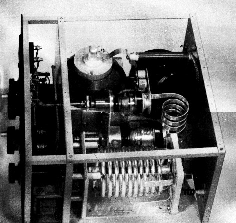
This view from the tank-circuit side shows the tapped pi-network coil and the vacuum input and output capacitors. The capacitors are mounted on an aluminum bracket fastened to the tube compartment. The plate blocking capacitor-four units in parallel-mounts on a plate fastened to the hot terminal of the input tuning capacitor. The plate choke is mounted on the rear wall. The chimney is around the tube in this photograph.
This bottom view gives a glimpse inside the grid compartment, upper left. R.f. input is through the coax connector on the rear wall and a short length of coax into the shield box. Power leads come in through the socket and high-voltage connector at the center, where they are enclosed by a small aluminum shield mounted on the rear wall. All except the high-voltage lead and leads to the blower motor go through the conduit (running alongside the bottom of the tank coil assembly) to the front of the unit. The high-voltage lead goes through shielded wire to the plate choke. Those to the blower are also shielded.
The front panel shows that two meters are used, though one is dual purpose. The plate current meter has a full-scale reading of two amperes; however, the maximum plate current that can be drawn is 1 ampere using the single tone test (into a dummy load). The dual-purpose meter is one milliampere full scale and is used in combination with a switch and shunts to read grid current at 1 ma. full scale, grid current at 100 mA full scale, or screen current at 100 mA full scale. The one-milliampere scale is used to monitor s.s.b. AB1 operation so as never to drive into grid current. The 100 mA grid current scale seems to be (and is) in direct contradiction to the statement that the control grid can dissipate no power. The truth is that from ½ to 1 watt can be handled, but this leaves no margin of safety. The rating of zero dissipation still stands.
Although AB1 operation minimizes the generation of harmonics, standard TVI-proofing techniques are used throughout. All leads leaving the shield enclosure not normally carrying r.f. are shielded and bypassed at both ends. Leads to the front panel from the compartment that shields the power-input socket are carried through the r.f. enclosure in a length of h-inch conduit.
Two filament transformers in parallel are used to supply heater power. This was done because no single transformer of suitable capacity was available to fit into the space allotted. The transformers have a total capacity of 12 amperes to supply a heater requiring 12.5 amperes. However, the overloading is considered negligible.
In operation the amplifier has proved to be quite stable. The 100-ohm resistor between grid and ground undoubtedly contributes a great deal to this stability. However, a change in layout, even though minor, could alter the picture. As always, each new design must be checked for parasitics and be debugged if necessary. Slight changes in an old design in effect make it a new one.
The author wishes to thank Vern Olsen, W6INJ, for the use of the photographs which show the construction of the very neat amplifier built by him.
Raymond F. Rinaudo, W6KEV.