Transistor audio for mobile rigs
A compact 6 meter unit.
One of the most immediate applications for transistors in ham radio is in mobile equipment where compactness is of more than ordinary importance. The practical possibilities have become definitely significant since transistors capable of handling 10 watts of audio were made available. Not only do the transistors themselves occupy little space, but the size of the power supply can be reduced since the transistors obtain their d.c. input power directly from a 12-volt car storage battery. An example of what can be done in the way of miniaturizing is illustrated in the photographs which show the details of a 15-watt 50 Mc. transmitter with an all-transistor audio section. The whole thing is contained in a 3 × 5 × 9 inch aluminum box (a 3 × 5 × 9½ inch aluminum chassis makes a satisfactory substitute). In my installation a Heath 260 V 60 mA vibrator unit supplies the r.f. section.
Circuits
The r.f. circuit shown in Fig. 1 is straightforward, beginning with a 25.1 Mc. third-overtone crystal and the first triode section of a 12AT7. The plate is slug-tuned to 25.1 Mc. and the output is fed to the grid of the other triode section of the tube which doubles frequency to 50.2 Mc. Ample drive is obtained at the grid of the 6417 for proper Class C operation. A balanced tank circuit is used in the output of the final so that neutralization may be easily added if found necessary. The output link circuit is tuned with a 100 pF variable.
The audio section is a modification of a design suggested by one of the transistor manufacturers for loudspeaker drive. The speech amplifier, which has three stages using 2N 107s, has enough gain for a crystal or high-impedance dynamic microphone. The Class B modulator using a pair of 2N256s is driven by a 2N255. The third 2N107 is used with the collector grounded to match the low-impedance input of the 2N255.
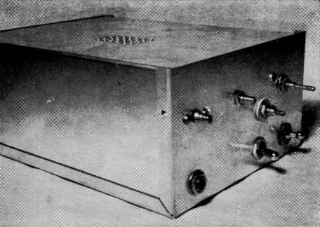
Controls along the top, from left to right, are for C2 and C1, and the slugs of L2 and L1. The microphone jack and the two toggle switches are at the bottom.
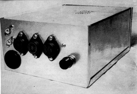
The three power transistors are mounted externally on the rear end of the aluminum enclosure. The phono connectors are for receiver input and antenna, with the r.f. power-supply connector below. The control to the right is for audio gain.
Construction
Most of the constructional details will be evident from the photographs. There are doubtless some who will want to do a fancier job. The r.f. section is at the front, with the tubes mounted horizontally from an aluminum partition. This partition is spaced just far enough to the rear to make room for the slug-tuned coils and the output tank circuit. The crystal is soldered directly to the oscillator tube pins.
The audio section occupies the remainder of the space. Small components are supported on a terminal board. The two audio transformers are mounted alongside the 6417 with their windings at right angles. A Z-shaped shield separates them from the other audio components.
The three power transistors are mounted externally to provide as much cooling as possible. Since the collectors of the 2N255 and 2N256 are connected to the metal shells, these transistors cannot be mounted directly on the chassis. I insulated them with sheets of asbestos packing about 1/16 inch thick. They could also be mounted on insulating studs to space them from the chassis. It should also be noted that both sides of the microphone circuit must be insulated from ground. The shield of the microphone cable is connected to the second insulated terminal of a "three-way" microphone plug.
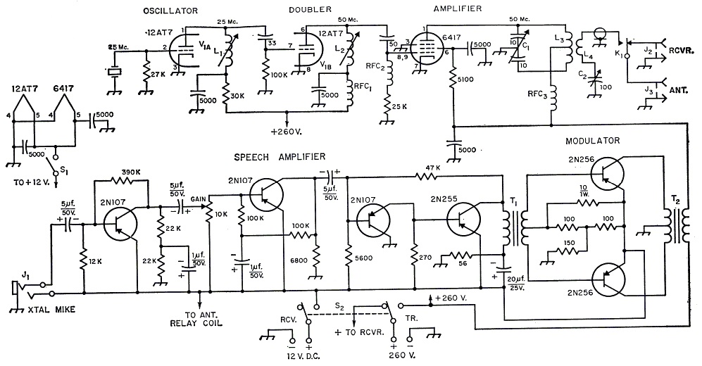
Fig. 1. Circuit of the 15 watt mobile rig with transistorized audio section. All r.f. bypasses are disk ceramic. R.f. coupling capacitors may be mica or ceramic. Capacitors marked with polarity are electrolytic. All resistors are ½ watt.
| C1 | Miniature butterfly, 11 pF per section (Johnson (160-211). |
| C2 | Midget variable, 100 pF. (Hammarlund MAPC-B100). |
| J1 | 3 circuit microphone jack (see text). |
| J2,J3 | Phono jack. |
| K1 | Midget antenna relay (Advance AM2C or similar). |
| L1 | 18 turns No. 18 enameled close-wound on ½ inch iron-slug form. |
| L2 | 5 turns No. 18 enameled close-wound on ½ inch iron-slug form. |
| L3 | 12 turns No. 12, ½ inch diam., self-supporting, tapped at center. |
| L4 | 4 turns insulated hookup wire around center of L3. |
| RFC1,RFC2,RFC3 | Approx. 7 µH. (Ohmite Z-50 or equivalent). |
| S1 | S.p.s.t. toggle switch. |
| S2 | D.p.d.t. toggle switch. |
| T1 | Transistor driver transformer (Triad TY61-X). |
| T2 | Modulation transformer - see text. (Thordarson 24571 speaker transformer in reverse). |
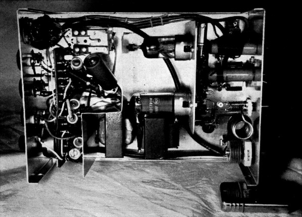
Looking down into the transmitter enclosure. The r.f. section is to the right. The 12AT7 oscillator-doubler (above) and the 6417 final (below) are mounted horizontally from a shielding partition. The crystal is soldered directly to the oscillator-tube socket prongs. The antenna relay is in the upper left-hand corner.
A speaker transformer connected in reverse is used as the modulation transformer.(1) The 5000 ohm tap on the primary is used for the secondary. The 16-ohm secondary is used as the primary. The winding has taps at 4 and 8 ohms, and it should be noted that since the impedance ratio is proportional to the square of the number of turns the center tap will come at the 4-ohm tap, not the 8-ohm tap.
Adjustment
I did not include a meter, but adjusted the r.f. section for best output with a field-strength indicator. The oscillator and doubler can be checked by listening on a receiver while adjusting the slugs. There will be an increase in signal strength when the slug is adjusted through resonance. If there is any fundamental-frequency instability in the final amplifier, a small neutralizing capacitor made with twisted wire can be connected between the lower end of the tank and the grid of the tube. I didn't find neutralizing necessary.
Depending on the rating of the supply, the final may be loaded up to a plate current of 50 mA. The modulator should draw about 10 mA idling and swing up to peaks of about 1 ampere on voice. It supplies more than adequate power for 100 per cent modulation of the final at full loading. It is important that the change-over switching system provide for turning off the 12 volt supply to the transistors during stand-by periods so that the transistors will have an opportunity to cool off. With the arrangement shown in Fig. 1, no difficulty from overheating has been experienced.
Using a vertical antenna on the car, ground-wave contacts as far as 20 miles have been made with 89 reports. The rig will fit neatly under the dash of most cars and will give many miles of mobile v.h.f. fun.
Notes
John O. Galloup, W8PYQ.