A New Receiver Tuning Principle
Wide-range British receiver with interesting features
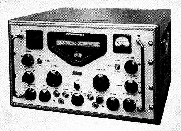
This British communications receiver has several unusual features not to be found in receivers built in the U.S. Each division of the top scale represents one kilocycle; this film scale is five feet long! The dark square at the left, matching the meter on the right, is a grille for the small monitoring loud-speaker.
Recently VE7AIK wrote to us to ask what we thought about the Racal RA-17 receiver, and we could only answer that we didn't think anything because we didn't know anything about it. This surprised VE7AIK no end, and he promptly sent us a flyer he had on the receiver. This in turn prompted us to get in touch with the manufacturers, Racal Engineering Ltd., Western Road, Bracknell, Berkshire, England.
The RA-17 Communications Receiver is expensive and it is made in Europe, so it isn't likely that we will see very many in the United States. The receiver is handled in Canada by Instronics Ltd., Stittsville, Ont., so some of our VE neighbors may be telling us about it over the air in the near future. The manufacturer was kind enough to forward enough information for us to pass along on what we think is a novel and interesting approach to receiver design.
Perhaps the outstanding feature of the receiver is the tuning method. The RA-17 has continuous coverage from 1 to 30 Mc. Referring to the photograph of the front panel, the large knob below the right side of the dial face is labeled "Megacycles"; it is set to the megacycle range you wish to tune. For example, the little dial face in the photograph indicates " 2," so the receiver is currently set to tune 2 to 3 Mc. The setting of this dial is not critical! (One would expect it to be very critical, so why it isn't will be explained later.) You then tune the range with the left-hand large knob and read the frequency from the horizontal scale. That horizontal scale is a strip of film 60 inches long, with a calibration mark every kilocycle. To change bands you merely turn the " Megacycles" knob to the right range and, to confuse you a little more, no switching is involved!
Since this tuning device is so unusual, perhaps it had better be described before we get on with the rest of the receiver. The block diagram of Fig. 1 shows what is used in the front end of the receiver. The v.f.o. tunes 40.5 to 69.5 Mc., and its control knob is the one tied to the " Megacycles" scale on the panel. Let's assume that the v.f.o. is set to 50.5 Mc. Although all of the harmonics of the 1-Mc. crystal will be hitting the second mixer, the signal in the plate circuit that gets through the 37.5-Mc. filter will be the beat with the 13th harmonic (13 Mc.; 50.5 -13.0 = 37.5 Mc.), and this 37.5-Mc. signal is applied to the third mixer. In the signal channel from the antenna, a signal at 10.5 Mc. would beat with the 50.5-Mc. v.f.o. and be heterodyned to 40.0 Mc., pass through the first i.f. stage and enter the third mixer. In the third mixer it would beat with the 37.5-Mc. energy to give a signal at 2.5 Mc., which could then be tuned in by the 2- to 3-Mc. receiver. (The 2- to 3-Mc. receiver tuning is tied to the 60-inch long scale that reads "Kilocycles.") It should be apparent that under the above conditions signals in the range 11 to 10 Mc. would be heterodyned to the range 2 to 3 Mc. and could then be tuned by the 2- to 3-Mc. receiver.
But if about this time you're wondering how they keep the v.f.o. stable at this high frequency, the answer is, "They don't have to." Suppose the v.f.o. drifted to 50.6 Mc. Its beat with the 13-Mc. harmonic of the crystal would be 37.6 Mc., and its heat with the 10.5-Mc. signal would he 40.1 Mc. The beat between 37.6 and 40.1 Mc. is still 2.5 Me., so although the v.f.o. drifted 100 ke. the signal stayed on the same frequency at the input to the 2- to 3-Mc. receiver.
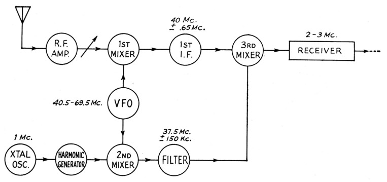
Fig. 1. Block diagram of the unusual tuning system in the RA-17 receiver. It features continuous coverage from 1 to 30 Mc. without switching.
The foregoing is not by way of implying that the RA-17 has oscillators that drift badly; all we can say about that is to quote (later) what the manufacturer claims. We did want to point out the ingenuity of the system, and the arithmetic was easier with a 100 kc. drift. To recapitulate a little, it should be apparent that the receiver stability depends upon the stability of the 1 Mc. crystal oscillator and the h.f. oscillator in the 2 to 3 Mc. tunable portion. Nothing is ever switched in the v.f.o. circuit, and it need be set only approximately to the right frequency for any given tuning range.
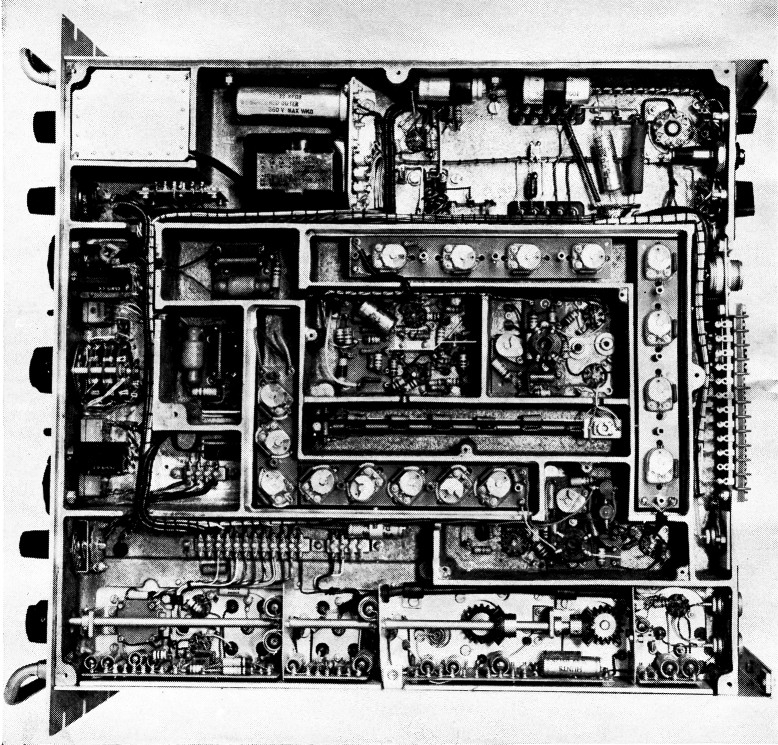
The die-cast aluminum chassis provides a rock-solid base for the RA-17. Pity the poor cricket that gets caught in there without a road map!
The arrow in the link between the r.f. amplifier and the first mixer in Fig. 1 is to indicate that tuned circuits are used here as well as some attenuation. Normally the front end might be set to a broad-band condition that requires no tuning. Should the signal be of such amplitude that it requires attenuation, 40 db. is available in steps of 10 db. Should a strong interfering signal be troublesome, the antenna range switch can be set to the appropriate band and the antenna tuning control rotated to peak the desired signal.
The tuning of the RA-17 is the major point of departure from conventional receiver design, and the remainder of the receiver incorporates what are currently considered to be desirable characteristics. Calibration check points every 100 kc. are obtained from the 1-Mc. oscillator and a regenerative frequency divider. Six degrees of i.f. selectivity (obtained at the third i.f. of 100 kc.) range from -6 db. band widths of 150 cycles to 8 kc.; the three sharpest band widths are obtained through the use of crystal-lattice filters. Two a.v.c. characteristics are available: a fast a.v.c. with a 200-millisecond discharge and a slow a.v.c. with a 1-second discharge. The S meter can be switched to read either "r.f." or "a.f." level; this is probably our usual S-meter circuit for the r.f. level and a rectifier in the audio for the a.f. level.
An over-all drift of less than 1200 cycles during two hours after a cold start is claimed for the receiver, and after two hours it is said to be less than 200 cycles, which is about as close as one can read the dial.
The receiver is said to sell for around £ 400 (over $1000 in Canada), and as yet no U. S. distributor has been appointed. We have been told that the receivers are already finding their way into ham (and commercial) shacks around the world, and some day it may be possible for some of us to log a little operating time with them. In the meantime, there is no good reason why enterprising "do-it-yourself " amateurs cannot apply the tuning principle to homemade receivers and transmitters.