Two linear amplifiers
The PL-172 in Grounded Cathode and Grounded Grid.
Everyone knows "there's more than one way to skin a cat"; the following few pages demonstrate that "there's more than one way to build an amplifier around the PL-172."
The amplifiers show certain points of common thinking, such as ease of construction, complete shielding and filtering, and pi-network output tuning with a vacuum variable. They also show points of considerable difference, as meter switching vs. individual metering, blower within the unit vs. blower outside the unit, and coil switching vs. continuously-variable inductor. The use of grounded-cathode vs. grounded-grid circuitry is a difference, of course, but it is dictated more by the use of the amplifier than by the philosophy of the designer. The grounded-cathode circuit gives the ultimate in power sensitivity and requires only a watt or two of drive for full output.
The grounded-grid circuit is most useful where 75 or 100 watts of drive is already available, since most of the drive will get through to the antenna and not be wasted.(1)
The PL-172 is a forced-air cooled, 1000-watt plate dissipation power pentode. It is particularly attractive to the side-band man, because one of its features is low distortion and high output in Class AB1 operation. Although it uses an indirectly-heated cathode (6.0 volts at 7.8 amperes, warm-up time 2 minutes), it carries ratings up to 3000 volts on the plate. Slightly more power output is obtained when the suppressor grid is run at +75 volts than when the suppressor is run at cathode potential.
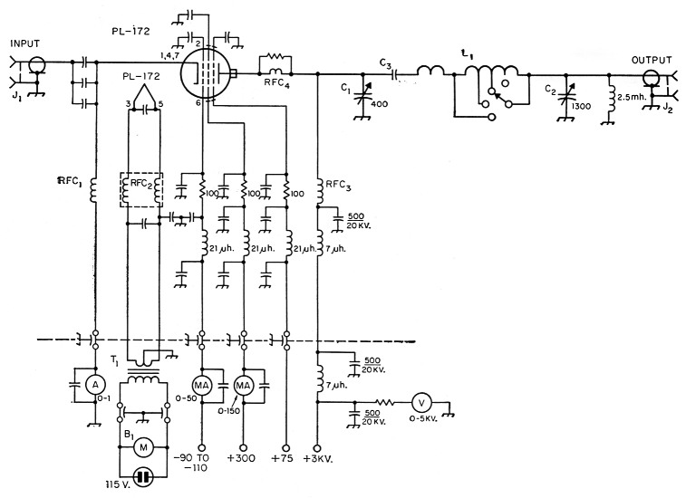
Fig. 1. Schematic diagram of the grounded-grid amplifier.
Capacitances are in pF, resistances are in ohms, resistors are 2 watt. Unless otherwise noted, feed-through capacitors are 500 pF 1500 volts (Centralab DA707) and fixed capacitors are 1 nF 3 kV disk ceramic (Central DD30-102).
| B1 | Dual blower assembly (W. W. Granger, Inc., Chicago, Ill., 1-68 X-50756 or equiv.). |
| C1 | 10 to 400 pF vacuum variable (Jennings UCS-10-400). |
| C2 | 1300 pF variable (Cardwell, surplus). |
| C3 | 1 nF, 10 kV ceramic. |
| L1 | Kilowatt switchable tank coil (B & W 850). |
| RFC1 | 4.3 mH 600 mA r.f. choke (Bud CH-569). |
| RFC2 | Heater r.f. choke (B & W FC-30). |
| RFC3 | 225 µH 800 mA choke (National R-175A). |
| RFC4 | 1 turn No. 10 wire ¾ inch diam. around 50 ohm carbon resistor (Globar CX) |
| The 7 µH r.f. chokes are Ohmite Z-50 and the 21 µH r.f. chokes are Ohmite Z-28. | |
| T1 | 6.3 volts at 10 amperes (Stancor P-6308) |
Since forced-air cooling is a part of the specifications of this tube (50 c.f.m. for 1000 watts plate dissipation), a special chimney and socket (PL- 184) are available. The screen and suppressor connections are made to rings around the base of the tube, and the socket features built-in by-pass capacitors for the screen and suppressor contacts.
Even if your personal taste and/or pocketbook doesn't run to an amplifier of the size the PL-172 will provide, it is hard to imagine that you won't find a few useful ideas in these pages.
Bill Frankart,2 W9KPD, built this grounded-grid linear amplifier around the PL-172 pentode. Major objectives were the use of readily available parts and a minimum of construction difficulties. The typical 100-watt side-band exciter will drive it to full output.
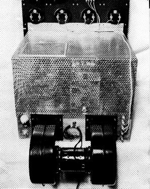
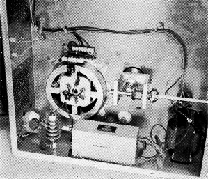
A dual blower assembly moves the air past the PL-172. The leads to the meters are brought out through feed-through capacitors (lower right), and the a.c. line to the heater transformer is filtered where it enters the chassis. Input jack and h.v. connection at lower left.
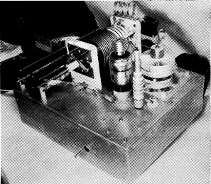
There aren't too many components above the chassis. A heavy copper strap from the base of the vacuum variable to the rotor of the output capacitor (mounted on insulators) insures that r.f. follows a single path and doesn't wander all over the chassis. Plate choke mounts on TV capacitor.
The special socket (Pentu PL-184) for the PL-172 provides for chimney cooling of the big bottle. Homemade deep chassis (17 × 15 × 5 inches) offers plenty of room for mounting the heater transformer and r.f. chokes and the many by-pass capacitors.
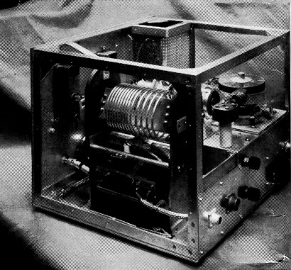
The variable inductor has been modified by moving the contact slide bar from the top to the bottom of the coil, to shorten the lead to the output capacitor. A silver-plated spring contact (scrounged from surplus relay) mounted on the small stand-off insulator attached to the coil support bar slides on the coil contact shoe in the 80-meter range. (See schematic, Fig. 2.) The 1000-pF heavy-duty mica output capacitor is to the right of the variable output capacitor under the coil.
Big tube is mounted on a shield box made by sawing in half a 17 × 10 × 5-inch chassis. Joints are masked in this view by end plate tying the two sections together. The blower is mounted on the shield box and intake is through the shielded meter section. The neutralizing tab is supported by the ceramic feedthrough at center. Plate tuning vacuum variable is held by heavy bracket and driven by counter dial through flexible couplings.
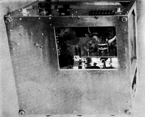
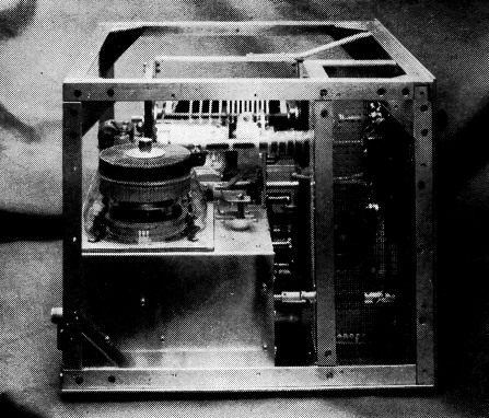
Access door under the amplifier is normally closed to maintain air pressure past PL-172. The two input coils are mounted either side of the band switch. Bias supply just visible at left through access opening. Knobs at top in photograph are for adjustment of 40-ohm heater rheostat and 5000-ohm grid-bias potentiometer. Normally bias terminal is connected to common (Fig. 2) but additional bias can be introduced through the connection if desired.
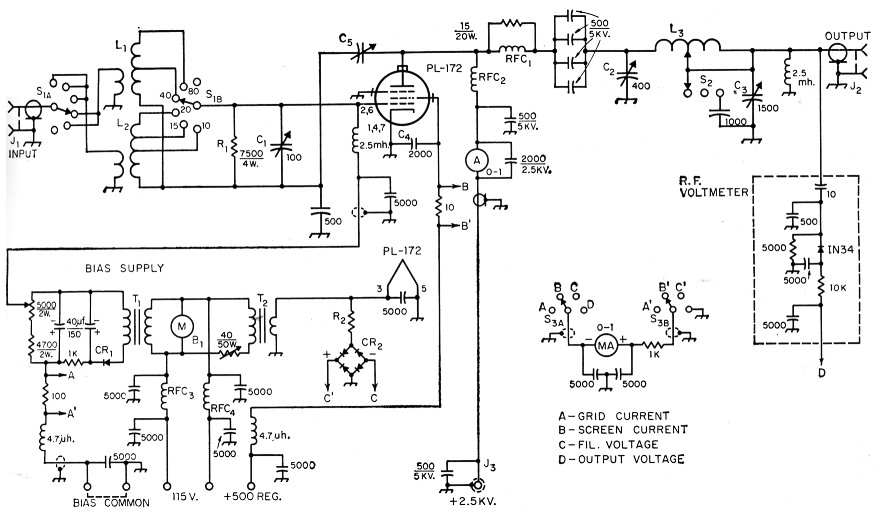
Fig. 2. Schematic diagram of the grounded-cathode amplifier. Unless otherwise noted, capacitances are in pF, resistances are in ohms, resistors are 1-watt, fixed capacitors are 1000-volt disk ceramic.
| B1 | 50 c.f.m. blower assembly (Fasco Type 50747-3N). |
| C1 | Midget variable. |
| C2 | Vacuum variable (Jennings UCS-10-400). |
| C3 | Transmitting type (Cardwell PL-8013). |
| C4 | Part of socket (Penta PL-l84). |
| C5 | Two-inch wide aluminum tab mounted near plate. |
| CR1 | 20 mA selenium. |
| CR2 | Meter rectifier (Conant Instr. Rect. Co. Type B-C). |
| J1,J2 | Coaxial receptacle, SO-239. |
| J3 | High-voltage receptacle (AN3102A-18-165). |
| L1 | 25 turns No. 24, 32 t.p.i., 1¼ inch diam., tap 10 turns from low end (B & W 3020 stock). Link is 3 turns No. 16 over low end. |
| L2 | 7 turns No. 16, 8 t.p.i., 1¼ inch diam., tapped 2 and 4 turns from low end (B & W 3018 stock). Link is 2 turns No. 16 over low end. |
| L3 | 8 µH variable inductor (Johnson 226-5). |
| R1 | Two 15,000 ohm 2 watt composition, in parallel. |
| R2 | 9K approx. Adjusted to give 0.6 mA meter reading when voltage of 6.0 measured at PL-172 socket. |
| RFC1 | 3 turns ¼ inch wide copper strap wound ¾ inch diam. outside 15-ohm 20-watt wire-wound resistor. |
| RFC2 | 225 µH 800 mA r.f. choke (National R-175A with 14 turns removed from low end). |
| RFC3,RFC4 | 35 turns No. 16 enam. close-wound on 3/8 diam. form. |
| S1 | 2 pole 6 position 2 section non shorting ceramic rotary switch. |
| S2 | Roller on L3 assembly. See photograph. |
| S3 | 2 pole 4 position non shorting ceramic rotary switch. |
| T1 | 150 V 25 mA secondary (Merit P3046). |
| T2 | 6.3 V 10 A secondary (Thordarson 21F1 2). |
Notes
- In a grounded-grid amplifier, more driving power must be supplied for proper operation than when the same tube is used in a grounded-cathode circuit. However, most of the driving power appears in the load along with the amplifier power, and the actual driving power dissipated in the amplifier is approximately the same regardless of the circuit.