Squelch for the NC-300
There are times when squelch is a nice thing to have on your communications receiver, as W3LIV points out. If you have an NC-300 and the desire to incorporate squelch, this article is your meat, although the principles are applicable to practically any receiver.
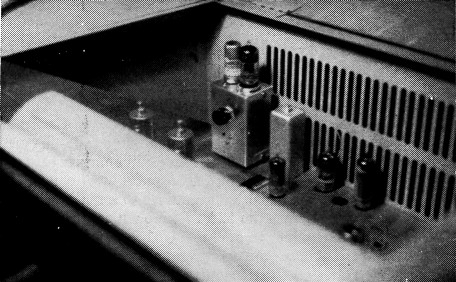
The squelch circuit plugs into the accessory socket of an NC-300. The sensitive relay and the 1 2AT7 plug into tube sockets on the top of the small box.
Plug-in accessory for a popular receiver.
Ever since converting a surplus SCR-522 two-meter receiver, I've been fascinated by the squelch control that was built into it. I'm one of those persons who spend a lot of time just listening, especially when working on some ff project in the basement. The rig is located there, and I like to keep the receiver tuned to one of the r frequencies that are kept fairly active by mem- hers of the local radio clubs. However, as everyone who has done a lot of listening knows, the steady hiss of the receiver and the ignition and other electrical noises can get pretty annoying when no signal is coming through.
Since the SCR-522 I've always wanted a communications receiver with a squelch circuit. Unfortunately, the use of squelch seems to be restricted to mobile receivers and the Gonset Communicator, and I never could get up nerve to operate on the station receiver to put one in myself.
After buying a National NC-300 and noticing all of the empty space inside of it, I decided that it would be no trouble at all to install a squelch circuit, utilizing the accessory socket of the NC-300. This socket has heater and B+ voltages brought to it, as well as the a.v.c. bus. There is a terminal strip on the back of the receiver where the audio output can be muted when -20 volts is applied through a 0.1-megohm resistor. The squelch circuit was built in a 2_1/8 × 1_5/8 × 3¼ inch Minibox (Bud CU-3001) that plugs into the accessory socket; short leads were run from the box to the muting terminals.
The Circuit
The schematic of the squelch unit is shown in Fig. 1. The receiver a.v.c. voltage is applied to the grid of one triode of the 12AT7. (The other triode isn't used.) When no signal is being received, the a.v.c. voltage is low and thus allows the tube to conduct. This causes the relay to pull in, and -22% volts is applied to the muting terminals of the receiver, causing the audio amplifier to be cut off. When a signal comes on, the a.v.c. voltage becomes more negative and cuts the 12AT7 off. The relay drops out, the -22% volts is removed, and the audio stage is allowed to operate normally.
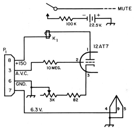
Fig. 1. Schematic diagram of the plug-in squelch circuit for the NC-300 receiver. Resistors are 1/2 watt.
K1 10,000 ohm sensitive relay (Potter & Brumfield SM5LS).
P1 Chassis mounting octal plug (Amphenol 86-CP8) 22V2-volt battery is Burgess U15 or equivalent.
The 3K variable resistor allows the unit to be set so that only a signal of sufficient amplitude will cause the squelch to trip. This setting can also be varied by the receiver r.f. gain control, as will be explained later. The 100K series resistor is recommended in the NC-300 instruction book. It becomes part of a voltage divider, since it connects to a resistor in the receiver and applies the correct voltage to the audio stage.
Using a v.t.v.m., it was found that the noise level kept the a.v.c. voltage at about -1 volt. It was decided to use a 10,000 ohm relay that would energize at 2.7 mA. With a plate load of 10,000 ohms and a grid voltage of -1 volt, the plate current of a 12AT7 triode is 4 ma. This gives the relay a good margin in available current and insures that the relay will energize and mute the receiver output. The noise level can increase until the a.v.c. voltage rises to a little over -1.5 volts before the 12AT7 tube will cut off and cause the receiver to operate. If the noise level is higher than this, the front panel gain control can be retarded to reduce the a.v.c. voltage.
Construction
The construction of the unit is not difficult. There is plenty of room, and no tricky techniques are required. The small 22%-volt battery is mounted on a piece of wood by means of a strip of aluminum and some small wood screws. The piece of wood allows the battery to clear the potentiometer and is held to the front of the box by three more wood screws. All wiring is direct and no terminal strips are used.
Adjustment and use
With the receiver r.f. gain control turned on full and the receiver tuned off of any station, adjust the 3K potentiometer until the receiver is muted and then turn the control back in the opposite direction until the receiver just becomes operative. The setting need not be adjusted any more unless the noise level changes. Now decrease the receiver r.f. gain until the receiver is muted. From now on the squelch circuit is controlled from the front panel. If the noise level is such that the potentiometer cannot be adjusted to mute the receiver, then just turn the r.f. gain down a little bit more.
The unit was found to operate very well. It's a pleasure to work around the basement and not have to listen to all of the ignition noise and receiver hiss. The receiver remains perfectly quiet 1 until a station comes on the frequency to which the receiver is tuned. When carefully adjusted, the unit will trip on fairly weak signals.