Feeding the simple antenna
Answers to many of the antenna questions asked most frequently by beginners will be found in this article. Included are descriptions of several simple antenna systems requiring no adjustmenf.
Basic radiators and their transmission lines.
In a Ppreviuous article(1) we said that antenna systems (antenna plus feed line or transmission line) are usually made to appear essentially as a simple resistive impedance at the transitter output terminals. A reason for this is that t is very difficult to build into a transmitter an utput circuit with sufficient latitude in adjust-ent to permit coupling into loads of a complex tore. It is usually much easier to adjust the antenna system so that its impedance falls within the range of values that a relatively simple transmitter output circuit can handle.
Transmission lines
A brief discussion of transmission lines should help in understanding what can be done in the antenna system to make it present a proper load to the transmitter. Perhaps the first question that should be answered is, " Why is a transmission line needed?" The answer is, of course, that we want the antenna to be in the most favorable spot available. If we bring the terminals of the antenna itself into the station where they can be connected to the transmitter terminals, we cannot avoid having most of the antenna close to buildings and other objects that will absorb much of the radiated energy. Therefore, we erect the antenna in the clearest space we can find and connect it to the transmitter through a transmission line. Transmission lines are designed to handle r.f. power with a minimum of radiation from the line. Therefore they can be brought inside the station with negligible loss from radiation.
The transmission lines used by amateurs usually have two conductors. In the coaxial-cable type of line, one conductor runs inside the other. The inner conductor is a wire. The outer conductor is a metal sleeve surrounding the inner conductor. Where mechanical flexibility is desired, the outer sleeve is a braid of fine wires. The two conductors are separated by a layer of insulating material.
In another type of line, two parallel conductors are held at constant spacing throughout their length by insulating spacers. In the familiar TV Twin-Lead or ribbon line, the insulation is entirely solid material. In other types of parallel-wire lines, insulating separators are spaced at intervals along the line and most of the insulation is air. Transmission lines of this type are called open-wire lines.
Characteristic impedance
At radio frequencies, a transmission line cannot be treated as a simple metallic connection between the antenna and transmitter. A transmission line has an electrical property called characteristic impedance. This impedance is expressed in ohms and its value varies with the type of line, size of the conductors, the spacing, and 'the kind of separating insulation. When one end of a transmission line is connected to an impedance equal to its characteristic impedance, this same impedance will appear at the other end of the line and it will be resistive, regardless of the length of the line. In such a case, the line is said to be matched. If any other impedance is connected to one end of the line, the impedance at the other end will vary with the length of the line.
Why match?
One consequence of a mismatch between the transmission line and the antenna is increased loss in the line. Also, since the input impedance of a mismatched line varies with its length, the length of the line may have to be cut to some critical length if the antenna system is to present a load impedance that the transmitter output circuit can handle. Only by chance will this length be the most convenient one to use between the transmitter and the antenna.
Matching systems
There are two general methods of providing a suitable load impedance for the transmitter. In one system, a transmission line with a characteristic impedance within the range of the transmitter output circuit is used and the antenna is matched to the transmission line so that the input impedance will be the same as the characteristic impedance of the line, as indicated in Fig. lA. In the other system, a mismatch between the line and antenna is allowed to exist.. At the transmit ter end of the line, a network (antenna tuner) is used that transforms whatever value of impedance that appears at the input end of the line to a value within the range of the transmitter output circuit, as shown in Fig. 1B. It should be emphasized here that this network does not match the antenna to the line. Therefore any line losses caused by mismatch still remain. Line losses in this case can be minimized by using a type of line that has low inherent loss - a line in which the conductors are large and the insulation principally air.
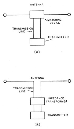
Fig. 1. Two methods of obtaining the desired load impedance at the transmitter output terminals. In A, the antenna impedance is transformed to match a transmission line whose characteristic impedance is the desired value. In B, the impedance of the entire system, including transmission line, is transformed to the desired value.
Matching the antenna and line
There are two ways of obtaining a match between the antenna and the transmission line. One is by using a transforming or matching device between the antenna and the line. The other is by using a transmission line whose characteristic impedance is the same as the feed-point impedance of the antenna. This value of impedance should, of course, lie within the range of the transmitter output circuit. Transmission lines are available that will match closely enough for most practical purposes the feed-point impedances of most of the commonly used simple antennas.
Center-fed dipole antennas
A dipole antenna (half wave length over-all), when fed at the center, has a feed-point impedance of approximately 70 ohms. It can be fed directly with either 70-ohm coaxial cable or 70-ohm Twin-Lead as shown in fig. 2. If coaxial cable is used, the outer conductor should be connected to the grounded side of the transmitter output termination.
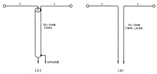
Fig. 2. Simple dipole antenna systems. A shows a coaxial-ca ble transmission line; a Twin-Lead line is shown at B. For the Novice portions of the 80-, 40- and 15-meter bands, L should have lengths of 63 ft., 32 ft. 6 in., and 11 ft. respectively. If one side of the transmitter output termination is grounded, this side should be connected to the outer conductor of a coaxial transmission line.
Grounded antennas and the ground plane
Quarter-wave-length grounded antennas (sometimes called Marconi antennas) may be fed directly with 50-ohm coaxial cable as shown in Figs. 3A and B. The ground connection should be a good one and be as close as possible to the base of the antenna. It is preferable to have the grounded antenna in a vertical position as in A, but if this is not practicable at the lower frequencies, it may be partly vertical and partly horizontal as shown in B. Dimension L should be the same as in Fig. 2.
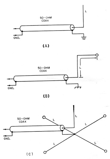
Fig. 3. Quarter-wave antennas. In A and B a good ground connection close to the base of the antenna is essential. In the ground-plane antenna of C, quarter-wavelength radials are substituted for the ground connection. The radial wires are run horizontally and the center junction should be close to the base of the antenna. The radials should be insulated. L should have the same lengths as in Fig. 2.
A disadvantage of the grounded antenna is the requirement of a short ground lead which often means that much of the antenna is in close proximity to energy-absorbing objects. This objection can be overcome by the ground-plane antenna shown in Fig. 3C. Here a system of insulated quarter-wave-length wires, usually at least four, running at approximate right angles to the antenna, are substituted for ground. Dimension L should be the same as in Fig. 2.
To be most effective, the ground-plane antenna should be vertical and the wires of the ground plane at least one quarter wave length above ground. For this reason, the use of the ground-plane antenna system is usually limited to the higher-frequency bands.
The folded dipole
Fig. 4 shows a folded dipole that provides a close match for 300 ohm Twin Lead. The antenna consists of two parallel half-wave conductors insulated from each other except at the ends where they are connected together. The transmission line is connected at the open center of one of the two conductors. Dimension L should be the same as in Fig. 2.
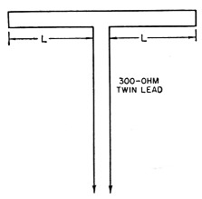
Fig. 4. The folded-dipole antenna. The spacing of the two conductors making up the antenna is not critical. Three-hundred-ohm Twin-Lead is often used, one conductor being cut open at the center, while the conductors are joined at the ends of the antenna. L should have the same length given in Fig. 2.
Multiband Antennas
Fig. 5 shows two types of multiband antennas that may be fed directly with 7O-ohm coaxial cable or Twin Lead. At A, separate dipoles, one for each band, are connected at the end of a single transmission line (2),(3) The individual dipoles should be spaced a few inches apart on spreaders so that they will not wrap around each other in the wind. Fig. 4B shows a trap antenna(4) which may be designed to cover the lower-frequency amateur bands, 80 through 10 meters. Several firms produce antennas of this type.
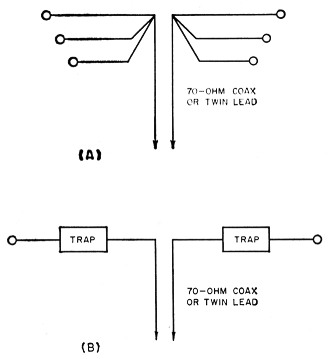
Fig. 5. Simple multiband antennas. In A dipoles with the lengths given in Fig. 1 are connected in parallel to one 70 ohm transmission line. B shows a trap-type multiband antenna. Details will be found in an earlier issue of QST.
Conclusion
In the foregoing applications, the impedance match will seldom be exact. However, experience has shown that the mismatch is not often great enough to throw the line input impedance out of the range of the usual pi-network output system. Also neglected is the consideration of feeding balanced antennas with an unbalanced line or from an unbalanced output circuit. Here again, the neglect may be of minor consequence in actual practice. The antenna systems described here have been widely used with complete success. For more exact methods of matching and the treatment of transformations between balanced and unbalanced circuits, reference is made to the ARRL Handbook and the ARRL Antenna Book.
Notes
- McCoy, "How to tune your pi-network final," QST, February, 1958.
- Berg, "Multiband Operation with Parallel Dipoles," QST, July, 1956.
- Richard, "Parallel Dipoles of 300 Ohm Ribbon," QST, March 1957.
- Buchanan, "The Multimatch Antenna System," QST, March, 1955.
Lewis G. McCOY, W1ICP.