High-power transistorized mobile power supply
125 Watts from 12 volts d.c.
In a mobile power supply, transistors have something more than novelty to offer - substantial output powers, high over-all efficiency, and exceptionally good voltage regulation. By the same token, there are things to watch out for, too. This article not only describes a husky mobile power supply but also outlines some of the precautions that have to be taken when using transistors in this application.
As fairly active radio amateur I have been engaged in mobile operation for the past several years. When I first came on the air I used transmitters of the home-constructed variety with power inputs in the order of ten to fifteen watts. About a year ago I purchased a 60-watt commercial all-band rig which I used for a time in conjunction with various dynamotor and vibrator power supplies.
Last fall, becoming quite interested in several articles I had read on the use of power transistors in high-efficiency d.c. to d.c. converters, I wrote to various component manufacturers in search of a practical circuit that would give 500 volts d.c. for the high-voltage output and about 250 volts d.c. for the low-voltage output. After collecting a notebook full of fine engineering data I found that I still lacked a workable circuit.
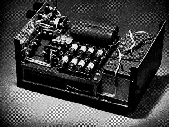
An inside view showing the silicon rectifiers, filter capacitors, high-voltage transformers, and control relay. The binding posts on the left wall are for bringing in the primary battery voltage. This view is from the bottom of the unit.
The only alternative left was to begin at the beginning of the data and by experimenting with breadboard circuits try to arrive at the desired results. This required two months of spare time. However, I did come up with very acceptable results which are set down here with the hope they will be of interest to others.
This supply has been in operation in my mobile installation for over two months and the results have been extremely pleasing, to say the least. The transmitter runs between 40 and 60 watts input to the final at all times.
Features
There are several outstanding features of this type of mobile power supply in comparison with either the dynamotor or vibrator supplies.
The first of these is the high over-all efficiency attainable at the higher power outputs. Assuming we have a mobile rig requiring 100 watts of d.c. plate power, there is a 20 per cent saving in input power with this supply over conventional methods.
The second feature is its reliability. Since there are no moving parts there are no maintenance problems. Of course, capacitors and resistors occasionally need replacement, but if the transistors are operated within their electrical and thermal ratings engineers have predicted a life expectancy in terms of years rather than hours for them.
Third, the supply is inherently self-protecting against overload. The fundamental circuit operation is such that when a short circuit or heavy overload occurs the oscillatory action ceases and the input current goes to a low value, where it remains until the trouble is corrected.
A fourth feature is the extremely good output-voltage regulation. This makes it especially attractive for use as a source of plate power for a single-side-band mobile rig.
Circuit
Fig. 1 shows the complete basic circuit of the unit, which is intended for use on a 12-volt negative-grounded automotive system.
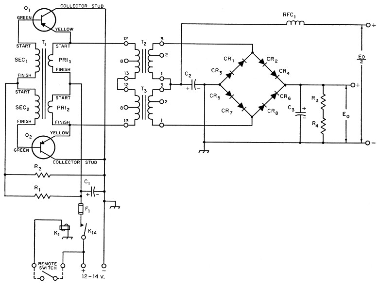
Fig. 1. Circuit of the heavy-duty transistorized mobile power supply.
| C1 | 2000 µF, 15 volts (2 paralleled 1000 µF electrolytics, Sprague TVA 1163). |
| C2 | 20 µF electrolytic, 350 volts. |
| C3 | 20 µF electrolytic, 600 volts. |
| CR1-CR8 | inc.-Silicon power diodes 400 V inverse peak, 500 mA d.c. (Sarkes Tarzian M500 or 1N1084). |
| F1 | Approx. 12-amp. rating (see text). |
| R1 | 3.3 Ω, 30 watts (3 paralleled 10 ohm 10 watt wire-wound). |
| R2 | 150 Ω, 2 watts, carbon, 10 per cent. |
| R3,R9 | 0.12 MΩ, 2 watts, carbon. |
| RFC1-2 | (7 millihenrys, 125 mA d.c. (Miller No. 691). |
| K1 | Starting relay, s.p.d.t., 12-volt d.c. coil (Potter & Brumfield MR series). |
| T1 | Special bifilar-wound toroidal transformer (see text). Core: 4-mil tape-wound "Deltamax" (Arnold Engineering Co. No. 37-4178-D4). Windings: (See text and Fig. 2). Pri: 64 turns (total) No. 14 Nyclad wire, bifilarwound. Sec: 88 turns (total) No. 26 Nyclad wire, bifilarwound. |
| T2,T3 | High-frequency filament transformer (see text). |
| Q1,Q2 | PNP power transistors (Delco type 2N278 or equivalent). |
The transformer labeled T2, a specially wound toroid, is the heart of the supply. Fig. 2 shows how the bifilar windings are arranged on the toroid.(1) The winding method is as follows:
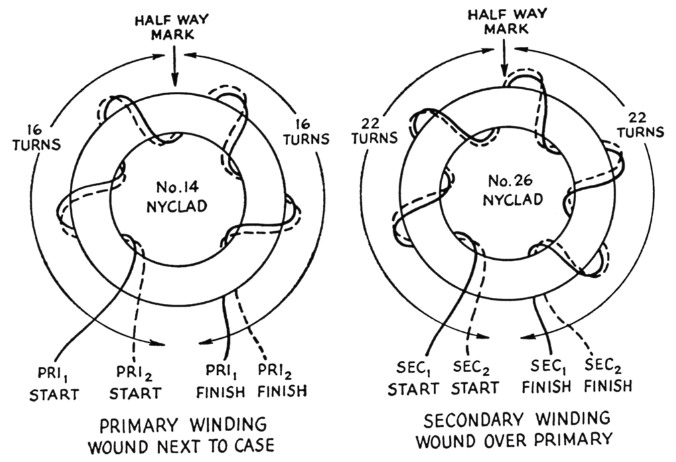
Fig. 2. Transformer winding details.
First, wrap the entire nylon-covered toroidal core with a layer of Scotch electrical tape, overlapping each turn about half the width of the tape. Keep the tape tight when winding.
In cutting the lengths of wire to be used for the primary and secondary windings allow 3½ inches per turn. This leaves plenty of wire left over for circuit connections.
Wind the primary first. For this winding, cut two lengths of No. 14 Nyclad wire each 112 inches long. Holding the wires parallel to each other, tape them together at their centers. Place this center mark against the core and begin winding the two lengths of wire side by side in both directions away from the center. Keep the wires tight and square off the turns around the core. Use even spacing and turns distribution so that the entire core is covered. Since there are only 16 turns in both directions away from the tape mark it is not difficult to end up with the correct number of turns on the core at the point directly opposite the starting mark. Cover the entire primary winding with two layers of Scotch tape.
Then, with two lengths of No. 26 Nyclad wire each 150 inches long, wind the secondary directly over the primary in the same direction as the primary, using exactly the same method. Cover the entire secondary with a single layer of Scotch tape. You should finish with 8 wires protruding from the tape. The designations and circuit connections for each are shown in Figs. 1 and 2.
In my model the toroid is held down to a piece of 4-inch thick phenolic by means of two plastic cable clamps. The wires are brought out to a lug-type terminal strip.
When dealing with this type of tape-wound toroidal core it has been found that the magnetic characterstics are affected by extreme heat or physical stress. We need not be concerned with the effects of heat since the maximum allowable operating temperature, about 200 degrees F, is well in excess of anything likely to be encountered in an amateur installation. However, the effects of physical stress are important because the windings can distort the core unless proper precautions are observed. Be careful not to crush the nylon case up against the core by using too much tension on the No. 14 wires when winding the primary. The secondary winding is wound with much lighter wire and is not apt to cause core distortion.
When the magnetic characteristics of the core are altered, improper switching of the transistors occurs and the over-all efficiency is lowered, resulting in increased transistor dissipation.
The step-up transformers T2 and T3 are surplus military-type high-frequency filament transformers. Their normal primary voltage is 108/115 volts a.c., single phase, with a secondary rating of 6.3 volts a.c., center-tapped, at 9.5 amperes. Their operating frequency range is from 380 to 1000 cycles per second.(2)
The remainder of the circuit is fairly straightforward and warrants little more discussion. The rectifiers employed are of the silicon type which are extremely efficient. Selenium rectifiers with proper ratings can be used with a slight drop in efficiency. The configuration is a center-tapped full-wave bridge.
Temperature Effects
Using the values and parts shown in Fig. 1 for the filter circuits, the ripple voltage at either d.c. output is extremely low at room temperatures. It was found, however, that after the supply had been left out in the cold weather for a time there was a noticeable increase in the ripple voltage at the d.c. outputs of the' supply. The reason for this is as follows:
Since we are dealing with square-wave voltages, the harmonic content is high. If the capacitor used to bypass the ripple components has too high an internal impedance at the higher ripple frequencies, small voltage spikes will remain on the B + leads. These spikes will get into the low-level audio stages of the receiver or transmitter and will be heard in the loudspeaker or over the air. The addition of RFC1 in the circuit of Fig. 1 reduced this effect.
If the difficulty in filtering persists, the builder could also try adding a suitable r.f. choke to the d.c. input lead. This choke should be capable of handling the normal full-load d.c. input current. In my installation I found that the ripple voltage on the battery leads did tend to creep into the audio circuits when the supply was very cold. This effect disappeared after the rig had been operating a short time.
One of the more serious problems with this type of power supply is failure to oscillate at low temperatures upon application of d.c. input voltage. This is because the current gain of the transistors is lowered as the temperature decreases. Resistors R1 and R2 are used to overcome this. These resistors bias the two transistors in the forward direction so there is a small initial current flow from emitter to collector when the input voltage is applied. Any small circuit unbalance will cause one transistor to conduct more heavily than the other initially, and since feedback is developed immediately, the oscillations begin. No difficulty whatever has been experienced in starting this supply, even under full load, when the car has been left out in near-zero temperatures for extended periods of time.
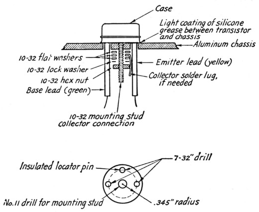
Fig. 3. Method of mounting the transitors on the chassis.
"Spiking" and voltage ratings
An oscilloscope connected across the base and collector of either Q1 or Q2 in Fig. 1 will show a square-wave voltage which has small spikes on the leading edges of the waves, as in Fig. 4. In a circuit that has not been properly designed these spikes can become extremely large in amplitude. Even though they are of short duration they can cause punch-through of the junction if the total voltage exceeds the transistor rating. The collector-to-emitter voltage wave forms are shown in Fig. 5. These voltage spikes represent switching transients and are due mainly to the effects of the leakage inductances in the windings of T1.
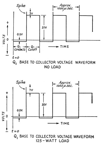
Fig. 4. Wave forms of base-collector voltage observed at the transistors. Note small "spikes" on the leading edges of the square waves. Rise and fall times for the square waves are less than 10 microseconds. Voltages shown are for 14 volts input.
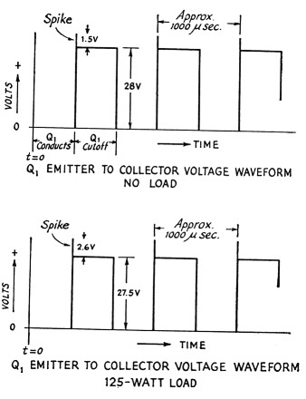
Fig. 5. Wave forms of emitter-collector voltage, under conditions corresponding to those of Fig. 4.
The importance of maintaining the transistor operation within the manufacturer's ratings at all times cannot be overemphasized. The Delco type 2N278 transistors have a maximum collector-to-base voltage rating of 50 volts. If this rating is exceeded, even for very short periods of time, gradual deterioration or instantaneous punch-through of the junction will occur and sooner or later the transistor will be useless. If this were to happen in the circuit shown in Fig. 1 the defunct transistor would conduct very heavily from emitter to collector and the base current no longer would control the conduction. Thus the circuit would remain in one state continuously and the d.c. current flowing from the battery through the primary winding of the transformer would become extremely large, since it would be limited only by the very low d.c. resistance of the primary winding.
For the above reasons it is evident that a fuse rated for the maximum normal input current (about 12 amperes for this supply) should be installed in the positive d.c. input lead, even though in normal operation the supply is inherently self-protecting so far as short circuits or heavy overloads on the d.c. output side are concerned.
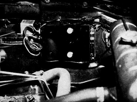
Mounted inside the front fender well of W1YOR's car, the transistorized supply is contained in a standard box measuring 8 by 6 by 3½ inches. Maximum total d.c. power output is 140 watts at 14 volts d.c. input-enough for a really husky mobile rig. Output and control connections are taken through the octal plugs on the left side of the box. The transistors are mounted on the box surface facing the reader.
It should be emphasized, however, that trouble of the above sort is not to be expected in this supply since the amplitude of these spikes is kept to a safe value by means of the bifilar windings on T1 and the large capacitor C1. Also, the circuit uses the Delco 2N278 transistors instead of the 2N277 type which are rated for 40-volt collectorto-base voltage.
Construction
The model shown in the accompany photographs is built in a Bud Minibox No. CU-3009 which is 8 inches long, 6 inches wide, and 3½ inches high. After the supply was constructed, masking tape was used to cover the transitors, power sockets, and terminals, and the entire case was sprayed with several coats of glossy black Krylon paint. This helps to radiate more heat from the supply.
Speaking of heat, a word is in order concerning the mounting of the transistors. It is extremely important to provide good heat transfer from the mounting bases of the transistors to the chassis. Their junction temperature must never be allowed to exceed the manufacturer's ratings or thermal runaway will occur and the transistors will become useless.
When mounting the transistors on the case be sure that the case is free from paint and dirt Coat both the chassis mounting areas and the copper bases of the transistors lightly with silicone grease (Amphenol No. 53-307 compound) before drawing them up snugly to the chassis. The detailed mounting method is shown in Fig. 3.
Actually, the layout of parts is not critical. A conventional box-type chassis may be used if desired. However, the larger the surface area the better, since that means better heat dissipation for the transistors.
Good construction techniques should be used. This includes good solder joints and the use of proper wire sizes and insulations for the various voltages and currents encountered in the circuit.
Installation
As mentioned before, heat is the prime limiting factor in high-power transistor operation. I have had my supply mounted in the engine compartment of the car since its completion. In the summer when the outside temperature is high this location may prove unsuitable. It has, however, one big advantage over any other location (other than one between the radiator and grille work) and that is that there is constant movement of air.
At this time I cannot prescribe the best location for the supply other than to say that maximum power outputs should be obtainable safely at ambient temperatures up to approximately 140 to 150 degrees F. This figure is based upon calculations only, and would involve amateur-type intermittent duty.
Performance data
Fig. 6 shows how the output voltage varies with load current, for input voltages of 12 volts and 14 volts, respectively. The excellent regulation characteristics are evident. Fig. 7 gives over-all efficiency curves for the two input voltages. These curves illustrate the tremendous advantages inherent in this type of power supply. In the author's view, it is well worth the money invested to obtain them.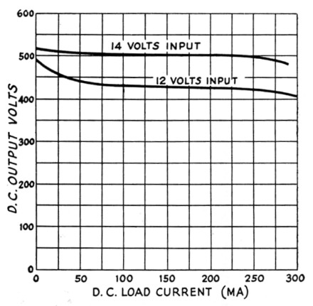
Fig. 6. Output voltage vs. load current, with primary d.c. input voltage held constant at the values shown. Output voltage measured at the high tap (E. in Fig. 1). Output currents may be taken from either the high or low taps, or both, so long as the total power does not exceed 125 watts at 12 volts input or 140 watts at 24 volts input.
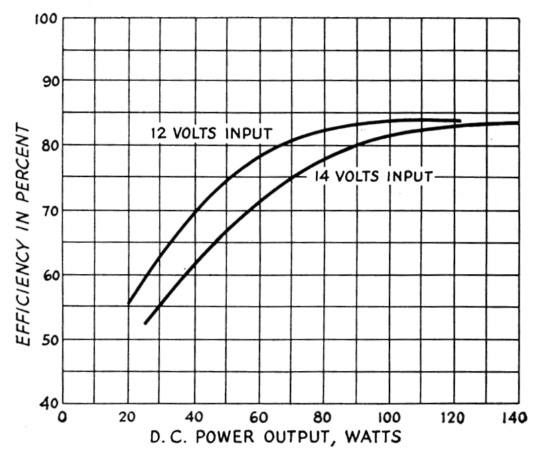
Fig. 7. Conversion efficiency vs. d.c. power output.
I would like to offer my thanks to Messrs. M. B. Hallam, C. A. Phaneuf, and A. Leverone, W1MGL, for their assistance during the experimental work conducted. The excellent photographs are the work of Ollie Noonan, W1FZO.
Notes
- The toroidal cores may be obtained from the Arnold Engineering Co., Marengo, Ill. The price is $3.95 each, but they must be purchased in lots of three because of minimum-order requirements.
- Transformers of this type can be obtained from the Electro Sales Co., 50 Eastern Ave., Boston, Mass., at a cost of $5.00 per pair f.o.b. Boston. Their stock number is 1070-4WA2, and the shipping weight is 4 lbs. There are several other windings on the transformers which are not used.
Richard P. Johnson, W1YOR.