Checking transistors
A simple unit for testing junction types.
With new uses for transistors in the ham shack being found almost daily, some method of testing these units becomes essential. The checker described here by W2TGP is easy to make and doesn't cost a fortune.
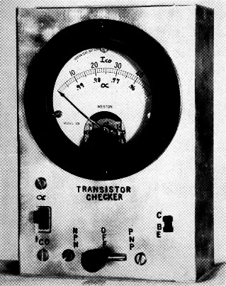
The transistor checker is built into a 4 × 6 × 2 inch aluminum chassis. S2 is to the left, S1 at the center and the transistor socket to the right.
With the increase in transistorized electronic gear finding its way into amateur use, the radio ham will find it necessary to supplement his present test equipment to more readily service these items. One of the most important problems confronting him is a means of testing transistors. Although the complete and. thorough test of junction transistors can be quite difficult, as well as requiring extensive test equipment, the approximate values of two of the more important transistor characteristics can be readily obtained with modest test gear. Making use of this fact, the transistor checker described here is an extremely useful and adaptable instrument despite its simplicity.
The rather delicate nature of the transistor so far as power dissipation is concerned is an essential factor when considering the importance of a transistor checker. In servicing electronic equipment that utilizes vacuum tubes, many technicians have relied on the substitution method of determining whether a tube was good or not; that is, if a particular stage in the device was inoperative and the tube was suspected, the trouble shooter would substitute a good tube and observe whether operation was restored. Now, if by chance, the tube was not at fault and another component was defective, this good tube might be subjected to abnormal operating conditions. However, the nature of the electron tube is such that many of these overload conditions for short periods do no damage to the tube. The technician then is satisfied that the tube is probably not at fault and the other components of the stage must be scrutinized.
The nature of the transistor is such that many overload conditions, even if for only short periods, are damaging to the transistor. Therefore, before the substitution of a good transistor is made in an inoperative circuit it is advisable first to determine that the operating conditions are satisfactory.
The two characteristics or parameters of the transistor that provide the best indication of the over-all performance of the unit are the collector current with emitter open (Ico) and the current multiplication ratio (α or β). The current multiplication ratio gives us a figure for the gain or amplification capabilities of the transistor, and the collector current with emitter open provides a figure that enables us to determine the transistor's performance in the presence of temperature variations and various circuit bias conditions.
Circuits
The collector current with the emitter open is sometimes referred to as the reverse current or saturation current. The symbol Igo is used quite often and it is the designation used on the transistor checker to indicate the position of the switch which provides this measurement. This current is measured in a manner similar to the connection shown in Fig. A. An N-P-N transistor is connected with the positive terminal of a battery connected, in series with a microammeter, to the collector and the negative terminal of the battery returned to the base. A P-N-P transistor is connected in a similar manner except that the battery and meter polarities are reversed. The resistor does not enter into the I. measurement; its purpose is to limit the current through the micro-ammeter when a defective transistor is checked. Most present transistors have an Ico of approximately 10 to 20 microamperes at room temperature. Also, Ico is very temperature sensitive; that is, it increases approximately two times for every ten degrees centigrade rise in temperature. Many transistors measured to date show a tendency for Ico to increase with age. The amount of increase depends largely on the temperature at which the units were aged. Most units display a tapering-off characteristic so that after a finite period a more or less final value for Igo is reached. In many cases this leveling-off has been at a value of approximately 20 to 30 microamperes. So normally one could expect a slightly higher Ico from a transistor that has been in service a year or two than would be obtained from a new unit.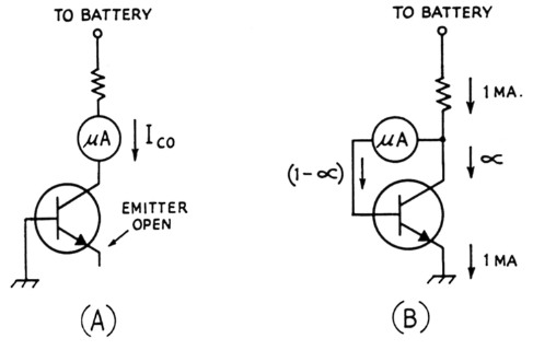
Fig. 1. Basic circuits (A) for checking the lco and (B) the α factor.
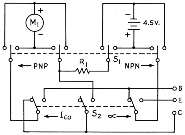
Fig. 2. Complete circuit of the transistor checker.
| M1 | 0-50 or 0-l00 microammeter (see text). |
| R1 | 4500 ohms total (1200 and 3300-ohm units in series, or equivalent), ½ watt. |
| S1 | Four-pole double-throw switch, center off position (see text). |
| S2 | Three-pole double-throw switch (see text). |
| Battery-total | 4.5 volts (three penlite cells). |
The gain factor a for the common base connection (which is also used to determine the gain factor β for the common-emitter connection) is evaluated with a circuit configuration similar to the one shown in Fig. 1B. The operation of the circuit is as follows: The total current (which is the emitter current) is one milliampere as determined by a 4.5-volt battery and a 4.5K resistor. The meter connected between the base and collector of the transistor provides a path for the base current and indicates the amount of base current necessary to maintain the emitter current of one milliampere. Thus, the meter reads 1 - a, and subtracting this value from 1 gives the value of a. The value a is the portion of emitter current that is flowing in the collector circuit and for most present transistors is between 0.95 and 0.99. The term β, which is the current multiplication ratio for the common-emitter connection, is equal to ![]() and is therefore between 19 and 99. It can be seen that as a approaches unity the current multiplication ratio of the common-emitter connection becomes very large and consequently the transistor is capable of high gain. In the majority of circuits in use today the transistor is operated with a common emitter.
and is therefore between 19 and 99. It can be seen that as a approaches unity the current multiplication ratio of the common-emitter connection becomes very large and consequently the transistor is capable of high gain. In the majority of circuits in use today the transistor is operated with a common emitter.
Construction
The transistor checker is entirely self-contained in a 4 × 6 × 2-inch aluminum chassis. The top of the chassis serves as the front of the checker. There is sufficient space inside the case to include the 4.5-volt battery. The useful life of the battery is essentially the same as the shelf life of the battery. The circuit diagram is shown in Fig. 2. The parts required are not many and no doubt little difficulty will be encountered in obtaining them. A 4-pole 3-position lever-action switch is used for the "test" switch; one side is the N-P-N position, the other side is the P-N-P position with the off position located in the center. The properties of N-P-N and P-N-P transistors are similar with the exception of the polarity of the applied voltage. In switching from one to the other it is necessary to reverse the polarity of the meter as well as the battery polarity. A rotary switch having the necessary 4 poles and 3 positions would serve as well. A 3-pole 2-position slide switch is used to transfer between Igo and a measurements. A rotary switch could be used here too, but the slide switch is more desirable because of its small size.
A 0-50 microammeter is used in the unit described and it permits a readings between 0.95 and 1. For those who might want to substitute a meter of different sensitivity a second choice would be a 0-100 microammeter. The range of a measurement would then be between 0.9 and 1. Other ranges of meters would not be as desirable because the more sensitive ones would not give enough range and the less sensitive ones would not provide enough accuracy in the high a region.
The calibration for the meter is given by the list of figures in the table. For the unit shown the actual calibration was scribed in ink on the face of the meter. Those who do not want to dismantle the meter or alter the meter scale can obtain the a or At values from the list according to the meter microampere readings.
Operation
The operation of the transistor checker is simple and straightforward. The only point to watch is the condition that might result in repeated meter overload. If a transistor with an open collector is checked for a, the meter would have 1 milliampere passing through it. Also, if a transistor with a shorted collector is measured for I,.,, the meter will again have a possible 1 milliampere passing through it. The N-P-N/P-N-P switch should be in the off position when a transistor is inserted in the socket to prevent the meter from being subjected to the 1 milliampere should the leads to the transistor be shorted during this operation.
| Meter Reading (µA) | α (Common Base Current Ratio) | β (Common Emitter Current Ratio) |
|---|---|---|
| 10 | 0.99 | 99 |
| 20 | 0.98 | 49 |
| 30 | 0.97 | 32_1/3 |
| 40 | 0.96 | 24 |
| 50 | 0.95 | 19 |
The transistor checker is designed particularly for the checking of junction transistors. The check of point-contact type transistors requires a slightly different approach. However, since there have been practically no point-contact transistors appearing in consumer electronic gear it was felt that the inclusion of the check of these units in the transistor checker would not be worth the effort.
The simple circuitry and the few components employed have resulted in a very useful and valuable instrument. The radio service technician, as well as the radio amateur and experimenter, will find the transistor checker a most worthwhile project.
H.F. PRIEBE, Jr, W2TGP.