The versatile standing-wave ratio indicator
Become a Bridge Expert in One Easy Lesson.
The s.w.r. indicator is a magical little instrument that is taken for granted = nowadays, although slightly more than a decade ago you would have been burned at the stake (or at least roasted on the podium) for even suggesting that =_ = such a thing was feasible. Common= place as it is today, however, the sad fact is that many owners don't know how to use s.w.r. information except in the most elementary ways. Read this article and you will see what we mean.
Judging by some of the letters received at Headquarters and by remarks heard over the air, not everyone who owns a standing-wave indicator knows the several different jobs it can do around the shack. If there weren't a strict taboo against it, this article would have been called "Getting the Most Out of the S.W.R. Indicator." (There aren't any editorial objections to getting the most out of anything; the objections are to the overworked cliché.)
To make sure that we're all talking about the same thing, let's review a little. Back in the days before coaxial feed lines were available, very few hams worried about the "standing-wave ratios" on their open-wire lines. A few studious types knew that such things existed on transmission lines, and a very few (non-operator types probably) could even make primitive approximations of the s.w.r. if their hands were forced. These primitive measurements consisted of trotting up and down the transmission line with a suitable indicator and finding the values of maximum and minimum voltage (or current). The ratio of the maximum voltage to the minimum voltage was called the "standing-wave ratio," and the hot shots called it the "v.s.w.r.", for "voltage standing-wave ratio." The resultant number turned out to be the same as the ratio of maximum current to minimum current. It meant very little to anybody but engineers.
When WW II came along it brought, among other things, the rapid development of microwaves and waveguide and solid-dielectric coaxial-line techniques. One thing you don't do on microwaves is to get yourself mixed up with high standing-wave ratios, because the losses mount up and components like magnetrons and such don't remain on their best behavior. First efforts at measuring the s.w.r. in waveguides and coaxial lines involved the old trotting-up-anddown-the-line technique (using probes and slotted lines) and, frankly, it was very slow and a pain in the notebook. The slotted line is useful for measuring some other things but if all you want is a number called the "s.w.r." then something direct reading is more desirable.
The direct-reading instrument showed up after a while, in the form of a device called the "directional coupler." The standing waves on a line are formed when all of the energy isn't absorbed at the load; some of it is reflected back and, with the later energy headed for the load, sets up the standing-wave pattern of maximum and minimum voltage (and current) points along the line. (The mechanics of all this is explained in many books, if you care to dig into it.) The directional coupler makes it possible to measure independently the energy in a line going from the generator to the load and also that reflected from the load back toward the generator. A high s.w.r. occurs when much of the energy is reflected, a lower s.w.r. is obtained when little energy is reflected, and the s.w.r. = 1:1 when no energy is reflected.
The value of the directional coupler should be obvious. If for some reason we want to know the s.w.r. in a line, we don't have to trot up and down it (which gets to be difficult in most practical antenna installations); we can make our observations at the transmitter end of the line. With more and more solid-dielectric coaxial line in use by amateurs, the directional coupler was a real boon. First one to appear was the Micromatch,(1) followed by the Twin-Lamp(2) and then the Monimatch(3) with its several versions. There is an allied device called the "s.w.r. bridge" that will measure the s.w.r.,(4) but it cannot be left in the line at all times the way the other devices can. It does, however, have an excellent place in the scheme of things.(5)
Why know the S.W.R.?
But what good are these devices? Smart hams could always tell when they had power going out the feed line; they used r.f. meters (thermocouple or hot-wire type, depending on the era) when they were in the chips, and they used flashlight bulbs or neon lamps when the groceries came first. But, you say, these modern transmitters with low-impedance output have to work into a line that has a low s.w.r. (Not necessarily so, but it's a popular misconception.) Phooey! Low-impedance output has been used for many years (ever hear of "link coupling"?), and we have been able to load transmitters, and properly, too. Suppose you have a Monimatch and a coax-fed dipole, and the indicated s.w.r. is 2.2; what do you do about it? (You tune up in the usual fashion, say you have "a fairly low s.w.r." and continue to operate, that's what you do!)
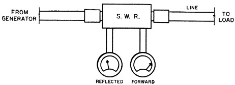
Fig. 1. Standing-wave indicators exist in several different forms and are identified by as many different names. The directional couplers discussed in this article all have three points in common. They are used in the line, they can handle the full transmitter power, and they measure the s.w.r. by comparing the Forward and Reflected powers.
What the S.W.R. indicator can do
The Micromatches and Monimatches consist of (1) an instrument that you connect in the line, (2) a two-position switch and (3) a meter. The switch points are labeled "Forward" and "Reflected," meaning that in the Forward position the meter reading is proportional to the power going toward the load, and in the Reflected position the meter reading is proportional to the power reflected (not absorbed) by the load. Whenever any reflected power is indicated it means that some of the power present is "reactive" or "apparent"; this may foul up your thinking and confuse your arithmetic if you aren't familiar with real vs. apparent power, or power factor, but don't let it throw you; the reflected power isn't dissipated in your transmitter, and all it ever does is run up your line losses some.(6)
Sometimes the meters are calibrated in watts, but more often you merely use the relative readings. The meter can be calibrated to indicate the s.w.r., because the s.w.r. can be found from a comparison of the Forward and Reflected readings. A ham with two meters could dispense with the switch and use a dual indicator like that pictured in Fig. 1. Don't let those fancy titles like "generator" and "load" scare you off; these are merely to show that the power source is at the left and the thing you're delivering the power to is at the right. The "generator" is usually your transmitter but it could be a driver stage or a signal generator; the "load" is usually the antenna but it could be the input circuit of a driven amplifier or a dummy load. Any of the power-handling instruments (Micromatch, reflectometer, Monimatch) have a negligible effect on the s.w.r. in the line to the left, but this isn't necessarily true of the resistive s.w.r. bridge referred to earlier.
In this enlightened age practically everyone knows what the meter readings will be when the load has a resistance equal to the impedance of the line. (The "impedance" of the line is determined by the physical and electrical characteristics of the line; you know RG-8/U to be 52-ohm line, RG-11/U to be 75-ohm line, and so on.) If the line is RG-8/U or some other 52-ohm line and the load is 52 ohms, when we turn on the generator the Forward meter will show something but the Reflected one will show nothing, as in Fig. 2A. The directional coupler is labeled "52-ohm S.W.R." to remind you that if it were designed for another line-impedance value we wouldn't get the same results (the Reflected meter wouldn't read 0).
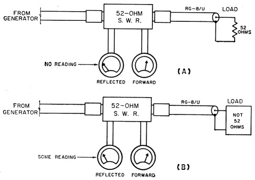
Fig. 2. (A) When the line is terminated in a load equal to the impedance of the line, the Reflected power is zero and the s.w.r. is 1:1.
(B) Any other terminaticn will result in some Reflected power.
This case with the load equal to the line impedance is of course a familiar thing to anyone who has used an s.w.r. indicator. The load doesn't have to have an ohmic resistor as shown in Fig. 2A; it can be, and more often is, the radiation (plus ohmic) resistance of an antenna. A standing-wave ratio of 1:1 means that there is zero reflected power, and the losses in the line are a minimum when the reflected power is zero. The length of the line should have no effect on the s.w.r.; the s.w.r. is determined solely by the relationship between the line impedance and the load.
When the load is anything other than a resistance equal to the line impedance, some reflected power will be indicated, as represented in Fig. 2B.
Using the directional coupler
Getting down to cases, here are some of the ways you can use the directional coupler:
1) To indicate resonance and proper coupling in the transmitter when no antenna coupler is used.
The way many hams use the things, by tuning the output amplifier for the highest indication of Forward power without burning up the transmitter. Manufacturers of s.w.r. indicators certainly don't object to this application, but a less-expensive indicator will serve just as well.
2) In the line between transmitter and antenna coupler.
Permits adjusting the antenna coupler to give an s.w.r. of 1:1 in the line between transmitter and coupler, desirable with pi-network output and when a low-pass filter is used. The low s.w.r. also minimizes losses in this length of line, although this is usually of minor importance in what is normally a short length. Remember that your adjustments do not affect the s.w.r. in the line between coupler and antenna. However, you can use the s.w.r. indicator in the line between coupler and transmitter to measure the s.w.r. on the line between coupler and antenna.(7)
3) To adjust coupling at input circuit of final amplifier, when amplifier is coupled to driver through coaxial line.
When this is done with driver and amplifier running at normal power, the resultant coupling condition for a midhand s.w.r. of 1:1 on the short coupling line also gives the best band width, which means you don't have to retune as often when changing frequency within a band.
4) To adjust matching section between antenna and line.
One of the very useful applications. The adjustment of a gamma match is a cinch with an s.w.r. indicator, and sheer guesswork without. With the antenna resonant (formula length) merely vary the gamma until a 1:1 or very low s.w.r. is indicated. The gamma match with an adjustable capacitor is the most convenient to use. If you can climb the tower you can use the s.w.r. indicator up at the antenna; if you have a light mast or tilt-over job that won't support you, rig up a string drive to adjust the capacitor with the antenna up in the air. The length of line usually isn't very important below 30 Mc., but above 50 Mc. the s.w.r. indicator is best used no more than a few wavelengths from the antenna. When the losses in the line begin to mount up, as they will in long lines at v.h.f., you will get indications of a match at the transmitter end of the line that aren't true at the antenna end. The extent of this effect is shown in Fig. 3. We've seen a coil of cable a few hundred feet long used as a dummy load for a v.h.f. transmitter; it made very little difference in the s.w.r. if the line was terminated or not.
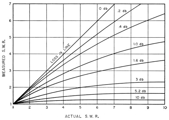
Fig. 3. Indicated s.w.r. as a function of true s.w.r. This clearly demonstrates the need for measuring the s.w.r. near the load when making matching adjustments at an antenna, if a long flossy) line is used. (From an article by John Lory, courtesy of Electronics magazine, a McGraw-Hill publication.)
5) To check antenna resonance.
Another of the more useful applications. If an antenna is used as the termination for a line, the frequency of minimum (not necessarily 1:1) s.w.r. is the frequency at which the antenna is a pure resistance (no reactance), and this is the resonant frequency of the antenna. Thus to find the resonant frequency of an antenna fed directly by coaxial line, it is only necessary to vary the frequency of the transmitter until the frequency of minimum s.w.r. is found. (Don't just look for minimum Reflected power; you have to make sure that the Forward power is still there, and this will probably require a few coupling adjustments at the transmitter as you run over the band.) If the minimum s.w.r. occurs at the high-frequency end of the band and you prefer to be peaked at a lower frequency, lengthen the antenna. If the minimum s.w.r. occurs at the low-frequency end and you have your heart set on the high, make with the cutters. You might be tuning a dipole made of No. 12 wire, or one of the new XTC4U specials (the one made from 14 beer cans and a piece of wet string); you can still use the technique. Just remember to make the resonance check with no matching section between the antenna and the line,(8) and be sure you find the minimum s.w.r. and not just the minimum Reflected power with some fixed transmitter coupling.
The above is based on the fact that near resonance the radiation resistance of an antenna changes slowly. Considering it to remain constant about the resonant frequency, any reactance added to the resistance will increase the s.w.r. when this antenna is used as a load for a line.
If you have any curiosity about your antenna, you can even get a fair idea of what the antenna impedance is, just by measuring the s.w.r. at resonance and then making an educated guess.
For example, suppose the s.w.r. turns out to be 1.6 at the resonant frequency, and you are using 52-ohm line. You know that the antenna impedance must be either 83.2 ohms (52 × 1.6) or 32.5 ohms (52 / 1.6), from the relation
Zo = R1 (s.w.r.) = R2 / (s.w.r.)
where
Zo = Line impedance
R1 = Resistive termination smaller than Zo
R2 = Resistive termination larger than Zo
Your educated guess would probably be the 32.5 ohms, in the case of a multielement beam.
If your meter reads Forward and Reflected power, the s.w.r. can be determined by the use of Fig. 4.
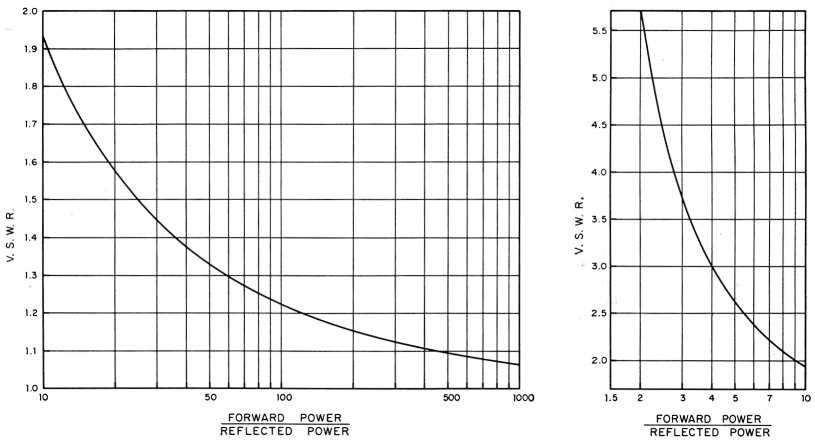
Fig. 4. Graph of s.w.r. vs. ratio of Forward to Reflected power. Use the chart on the right for low power ratios.
Effect of Harmonics
There may be occasions when the Reflected reading will run higher than the Forward. This doesn't necessarily mean that the unit has gone haywire; in most cases it will be an indication of a serious u.h.f. or v.h.f. parasitic oscillation in the transmitter. In the case of a c.w. transmitter, the Reflected reading may jump up to a high value as the key is closed and then drop down to a more normal value; this means that there is a momentary v.h.f. or u.h.f. parasitic oscillation as the key is closed.
When you are getting down to very low readings of reflected power, you have to avoid any appreciable spurious content in the transmitter if the load you are adjusting is frequency sensitive. In other words, if you are adjusting something that tunes, like a gamma match or an antenna coupler, it will give a proper termination for the line at only one relatively narrow band of frequencies. You will tune and tune and never get the s.w.r. down to 1:1 if there are a few watts of harmonics or overtones in the transmitter output.(9) These days most transmitters are fairly clean, but the point is mentioned on the off chance that one or two readers may beat their brains out trying to match up something that is matched all the time. Most hams don't try to match this close, but there are a few persnickety ones and we want them to be happy, too.
Notes
- Jones and Sontheimer, " The 'Micromatch,' " QST, April, July, 1947.
- Wright, "The 'Twin-Lamp,'" QST, Oct., 1947.
- McCoy, " The Monimatch," QST, Oct., 1956; QST, Feb., 1957.
- Pattison, Morris, Smith, "S.W.R. Meter for Coaxial Lines," QST, July, 1947.
- Corderman, "A Composite Test Set," QST, Dec., 1955.
- Goodman, "Losses in Feed Lines," QST, Dec. 1956.
- Grammer, "Universal S.W.R. Measurements With a Coaxial Bridge," QST, Dec., 1950.
- The line should be connected in the center of a halfwave antenna or in a current loop (point of maximum current) in a long wire.
- Grammer, "Note on S.W.R. Measurement," (Technical Topic) QST, May, 1952.
Byron Goodman, W1DX.