50 Kc Transistor-multivibrator frequency standard
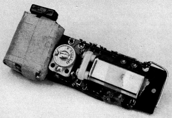
An experimental 50 kHz oscillator built on a small terminal strip. Battery, at left, is hearing-aid type, taped to assembly. The crystal is mounted horizontally over most of the other components, including the transistors.
The receiver calibrator described in this article is capable of producing signals at 50 kc. intervals up to 30 MHz with at least S7 strength at the latter frequency. Most of the circuit components may be found in the average ham's stock of parts. The transistors specified, chosen because of their 30 volt d.c. rating, are readily available at a reasonable price. The power supply may be two standard 6-volt dry batteries in series or, since the current drain is only approximately 3 mA, a 45 volt battery may be split into four sections, each good for several months' operation. The crystal is a standard NT plate designed for 32 pF operation at room temperature. A crystal having 50,000 ohms or less resistance is satisfactory.
A convenient method of mounting parts is shown in the photograph. The 1/8 inch bakelite mounting board is 1¼ inches wide by 4¼ inches long and has seven solder terminals spaced along each edge. The parts layout is very similar to the circuit diagram except that the crystal is mounted so it lies flat above the other components. When the calibrator is complete the mounting board may be attached inside the receiver cabinet.
For initial testing a milliammeter, bypassed with a 25 µF capacitor, should be connected in series with the battery. The battery should be disconnected immediately and the wiring rechecked if the current is more than 6 to 8 mA. The tank, L1C1, should be tuned for minimum current, which also should be the point of maximum r.f. output. The unit shown in the photograph uses a homemade universal-wound coil, which is probably not practical for the ordinary constructor. However, any combination of L1 and C1 that will tune to 50 kc. may be used; suggested values of standard components are given in the caption for Fig. 1. The circuit tuning may be adjusted by trying different combinations of parallel capacitors to give some range of adjustment around the approximate resonance value of 680 pF.
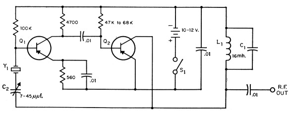
Fig. 1. Circuit of the 50 kc calibrator. Capacitances are in µF except where otherwise indicated; resistors are ½ watt; fixed capacitors are ceramic.
| C1 | Mica, to tune with L1 to 50 kHz; app. 680 pF with 16 mH coil. |
| C2 | 7-45 pF ceramic variable. |
| L1 | 16 mH r.f. choke or similar (Meissner 19-1995 suitable). |
| Q1,Q2 | Texas Instrument type 301. |
| S1 | s.p.s.t. (microswitch used in unit shown in photograph). |
| Y1 | 50 kc crystal (Knights type H-17T). |
When the unit is operating properly the current should be approximately 3 mA with the crystal in the circuit and approximately 6 mA with the crystal removed. The frequency may be zeroed with WWV at 5 MHz by adjusting C2.
The oscillator will operate at 100 kHz by changing C1 to 15 nF and L1 to 6 mH, and using any standard 100 kHz crystal (E, MT or NT plate).
Robert E. Berge, W9KRU.