Choosing capacitors selecting types for an S.S.B. exciter
This is an article about capacitors the whys and wherefores of making a selection among the many types and styles for a specific circuit application. The fact that the circuit discussed is that of a filter-type single-sideband exciter is incidental - it just so happens that this kind of equipment offers a variety of interesting capacitor situations: audio, i.f., r.f., d.c. blocking and filtering. (Nevertheless, it's a simple and practical s.s.b. unit.
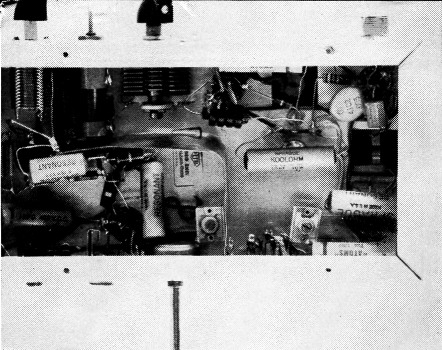
A sheet-copper shield partition separates the 455-kHz. oscillator and balanced modulator section from the remainder of the unit. The audio connector and modulator balance control are on the rear (top, in this view) wall of the chassis.
Capacitors are used in an electrical circuit for one or more of three reasons: they may allow the transfer of d.c. voltage while attenuating a.c. voltage (filtering); they may pass alternating current while blocking direct current (coupling); and they may store energy electrically for later use (tuning or other storage application). Taking a typical amateur-designed single-sideband exciter as an example, this article discusses the exciter's use of capacitors and points out some considerations and short cuts often overlooked.
The exciter
This exciter description is furnished only to give an over-all view of the unit, for few amateur builders make an exact copy of any design. The circuit is given in Fig. 1.
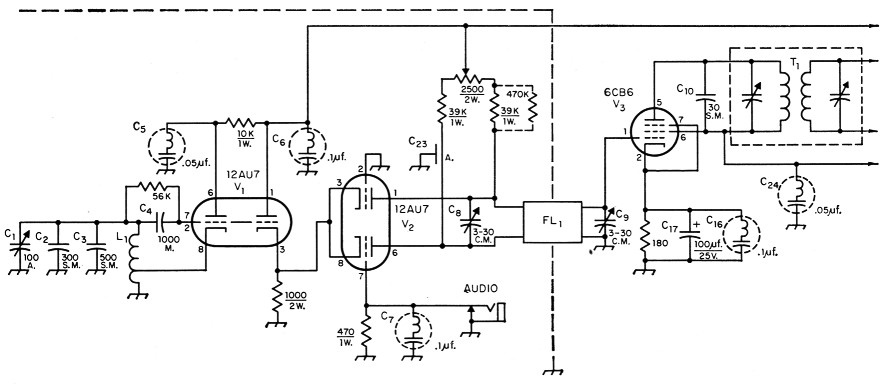
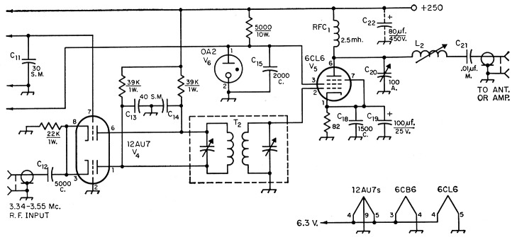
Fig. 1. The s.s.b. exciter circuit discussed in the text. Unless otherwise indicated, capacitances are in pF, resistances are in ohms, resistors are ½ watt.
| C1,C20 | Air variable. |
| C2,C3,C10,C11,C13,C14 | Silver mica. |
| C4,C21 | Mica. |
| C5,C6,C7,C16,C24 | 455 kHz resonant bypass (Sprague type 72P). |
| C8,C9 | Compression-mica trimmer. |
| C12,C15,C18 | Ceramic. |
| C17,C19,C22 | Electrolytic. |
| C23 | Air fixed (See text.) |
| Fl1 | Mechanical filter, 455 kHz. (Collins F455A-3). |
| L1 | Broadcast-band superhet oscillator coil (Meissner 14-1033). |
| L2 | App. 30 µH (730 ohms reactance) for 72 ohm load; app. 25 µH (610 ohms reactance) for 52 ohm load. |
| T1 | 455 kHz interstage transformer (Meissner 16-6659 used with C10 and C11 added). |
| T2 | 4.5 MHz. TV sound i.f. transformer (such as Miller 1466). |
A variable-frequency 450 to 455 kHz oscillator and buffer (V1) is cathode-coupled to a grounded-grid balanced modulator (V2). One grid is fed audio from a 500 ohm tap of an outboard audio amplifier. The two sidebands present in the plate circuit feed a Collins 455 kHz mechanical filter, the upper or lower sideband being selected by tuning the v.f.o. respectively below or above the filter pass band. As the wanted sideband is attenuated more than 20 dB with the old-style filter used here, a 455 kHz. amplifier (V3) is de sirable. (The unwanted sideband is attenuated more than 80 dB, or 100,000,000 times.)
An outboard 3340 to 3550 kHz v.f.o. feeds the cathodes of a balanced modulator (V4), one grid being fed the 455 kHz single-sideband output of V3. Tuned transformer T2 selects the 3800 to 4000 kHz output desired, which in turn is amplified by V5 and presented to the antenna or amplifier as a 23 watt peak signal.
No exceptional performance is claimed for the exciter, though under crowded 75 meter band conditions distances greater than 800 miles have been worked using it alone.
Capacitors at audio frequencies
The audio frequencies most commonly encountered in an amateur radio telephone transmitter are 60 Hz. for the filament or heater circuits, 120 Hz. ripple on the high-voltage supply, and various strengths of audio signals between 200 and perhaps 10,000 Hz. (Most side-band transmitters strongly reduce audio signal strength level outside of the 300 to 3500 Hz range.)
Cathode by-pass capacitors C17 and C13 were included only to reduce capacitive hum pick-up from the a.c. operated heaters. If operation of the V3 and V5 amplifiers were perfectly linear, hum pick-up by their cathodes would have no effect because the tuned output circuits would not pass any measurable amount of 60 Hz. But no amplifier is perfectly linear, so any hum will at least slightly modulate the amplified signal. Capacitors C17 and C18 are insurance against hum pick-up. Their use in minimizing demodulation effects is described in the "Capacitors at High Frequency" section later in this article.
Modulation of the oscillator or "linear" amplifiers may also occur from 120 cycle ripple in the high voltage source. The conventional "well-filtered" supply in use at first with this exciter had only ½ per cent ripple, but it did cause some modulation. Adding 80 µF (C22) in parallel with the existing filter reduced the hum modulation below measurable level. More capacitance is available in a single unit if needed, 200 µF at 250 volts or 125 µF at 450 volts being common in electrolytic capacitors.
The same considerations also apply to screen voltages. While dropping resistors and large capacitors could have been used, regulator V6 was chosen to establish the screen voltage of V, and plate and screen voltages of V3 independently of the aging or other variations in these two pentodes.
The only other capacitor having an effect at audio frequencies is C7. This capacitor paralleling the 470 ohm audio terminating resistor desirably reduces the modulation level above 3000 Hz., depending somewhat on the output impedance of the external audio amplifier.
Capacitors at 455 kHz
The most unusual part of the design is the use of resonant capacitors for coupling and bypassing at 455 kHz. The 0.05 and 0.1 µF Sprague resonant capacitors are particularly well-suited to designs using the Collins 455 kHz mechanical filters, showing a very low impedance across and bordering the filter pass band. The grounded-plate Hartley oscillator and buffer stages use them (C5 and C6) to hold the plates at ground potential and to filter the B line leaving the shielded area. This filtering is very necessary because the level of the unwanted signal inside this area is 80 db. higher than outside. C7 holds the grid (Pin 7) of V2 at 455 kHz ground while that grid is being modulated with audio.
Similarly, C16 and C24 bypass the cathode and screen of V3. One common gaseous voltage regulator problem is solved by C24, which provides good bypass action without adding enough capacitance to make V6 become a relaxation oscillator.
One precaution is and always should be observed when using resonant capacitors: be sure that the capacitor is biased or pulsed with a few volts during use. Charging of the capacitor is necessary for reliable operation and more than 10 volts is recommended, although two volts has been satisfactory in this design.
Fixed tuning capacitors such as C2, C3, C19, and C11 should have two qualities: stability and low loss. These are both met by use of silver mica capacitors. Parenthetically, C10 and Cu were needed in this circuit only because the particular transformer used (T1) did not tune to the filter pass band.
Variable tuning capacitors have two additional criteria: convenience and cost. Cost enters because good variable capacitors cost much more than good fixed capacitors. Convenience is more a question of how permanent the adjustment is to be. An APC style capacitor (CO is used to vary the v.f.o. frequency and uses about Yi the range of the capacitor to cover the pass band. A double-bearing capacitor would have been better, but the real limit on stability here is the oscillator coil.
The filter trimming capacitors, C8 and C9, would be much larger with the newer Collins filters, but compression mica types would still be suitable as very little adjustment is needed.
The balancing capacitor C23 posed a problem, as common differential capacitors detuned C8 and very little capacitance - less than 1 pF - was needed to the plate (Pin 6) of V2. The final solution was to bring a grounded but insulated wire near the plate lead.
The filter-type exciter discussed in this article fits easily on a 5 × 9 × 1½ inch chassis, in spite of an extra socket or so vacated after the final circuit was developed. The 455 kHz. v.f.o. (for side-band switching) and balanced modulator are at the left; the 455 kHz amplifier and mixer amplifier are at the far right.
The 6CL6 output amplifier (3.8 - 4.0 MHz) is at the front center.
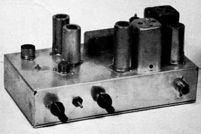
Controls along the edge are, left to right, 455 kHz v.f.o. tuning, slug adjustment for L2, output amplifier matching capacitor (C20) and coax input socket for the external v.f.o. signal.
Capacitors at high frequency
By-pass capacitors C18 and C18 do not have to be good bypasses at audio frequencies, although the stage is amplifying a modulated wave. Regulator V6 will stifle any tendency for screen demodulation, while C19 will not permit the no-signal to full-signal current shift in Vs to change the cathode bias at an audio rate. Thus C18 and C18 need to be good bypasses only at the output frequency. Ceramics are good choices for both fundamental amplification and harmonic suppression. Cathode demodulation in V3 is likewise minimized by C17.
Coupling capacitor C12 supplies a few volts of 3.5-MHz r.f. to the cathodes of balanced modulator V4. A ceramic capacitor is quite adequate.
Coupling capacitor C21 is in series with the exciter load and for this reason should have low series reactance compared with either 50 or 75 ohms. As only about 3 watts is transferred (about 20 peak volts) a 300-volt mica capacitor is adequate.
Capacitors C13 and C14 are balancing rather than strictly tuning capacitors. While there is a large frequency spread percentagewise between the 3.5 MHz. v.f.o. input and 4-MHz. output, it is well to have reasonably matched capacitors. If fixed capacitors are used, they should be of silver mica construction because of their availability in close tolerances.
The output matching (a better designation than "tuning") capacitor C20 is a conventional variable air type having the proper capacitance range for matching 50 or 75 ohms to the plate load of the 6CL6. The convenience and high voltage rating of inexpensive air capacitors were the deciding factors.
Summing Up
This list of examples shows many of the characteristics of capacitors that determine the selection of different types in different applications. There is no one best capacitor - each has it use.
Manufacturers of electronic equipment do not and should not always follow these examples. There is more than one way to obtain any electrical result, and the manufacturer as well as the amateur is always seeking the better way.
The brief check list below ends the discussion of capacitor application - some items are certainly important and all may be:
1) Capacitance
2) Tolerance
3) Stability
4) Temperature
5) Series Resistance
6) Series Inductance
7) Variable?
What limits?
8) D.C. Leakage
9) D.C. Voltage
10) Peak Voltage
11) Applied Frequencies
12) A.C. Currents
13) Size Weight
14) Vibration and Shock
15) Desired Life
16) Other conditions, such as mechanical strength, mounting, moisture conditions, corona, external fields, effects on external circuit, actions at harmonics, etc.
This information is particularly useful to the capacitor manufacturer, for then he can make intelligent recommendation of a satisfactory capacitor type.
Ratings, life and other characteristics
Pitfalls the manufacturer tries to avoid are those of (1) excess electrical voltages or currents that shorten life, (2) thermal, mechanical, or chemical conditions that may cause unacceptable changes, and (3) misunderstanding by the user of the actual electrical characteristics of the capacitor.
Every electrical or electronic part has planned life, whether one hundred, one thousand, ten thousand, or more operating hours at rated electrical conditions. Reducing operating voltage of capacitors will lengthen their life, a reduction to ½ rated voltage giving about 30 times longer life if no other adverse conditions are present. The expression
![]()
is often used as a life prediction. The actual voltage used for prediction should be the peak voltage, not d.c. or r.m.s.
Capacitors also have maximum current ratings. In spite of their remarkable efficiencies, capacitors of all varieties have some resistance and will transform electrical energy to heat in the form of PR loss. This effect is particularly important in power-supply filters and in radio-frequency circuits of transmitters; in these applications, currents may be higher than the circuit designer may anticipate. The basic problem seems to be the effect of the heat on the dielectric and, conversely, how to cool it. Because of this cooling problem, it is often better to use many thin capacitors in a power-supply filter than to demand all the microfarads in one package.
At radio frequencies, frequency as well as current becomes important. At low frequencies, current through the reactance determines the maximum voltage and must therefore be limited. Usually a maximum current is reached as frequency is increased, with still higher frequencies requiring lower currents because of greater resistive losses.
Temperature is generally very important. Where end of life is caused by some progressive chemical reaction, the rule that the speed of the reaction doubles with every 18° F. temperature rise applies. Some dielectrics become much better conductors at high temperatures, and then greater losses cause still higher temperatures and destruction. Other dielectrics change state; for example, common electrolytic capacitors freeze and wax melts, causing severe capacitance change. Almost all materials expand and contract with temperature change, and only the best construction will assure capacitance return near an exact value after a temperature cycle. Silver mica is good in this respect. Ceramic capacitors may be obtained with very nearly zero change ("zero coefficient") over wide ranges, and many of the accurate and low-loss uses of mica capacitors are being taken over by ceramic types.
Ceramic accuracy is usually tailored to the customer's needs, the commonest and cheapest capacitors having only a "guaranteed minimum value." More accurate and stable capacitors result from different ceramics, even negative-coefficient ceramics being available to compensate for temperature effects of other components on capacitance or frequency.
The discussion of resonant capacitors mentioned another general factor: the minimum peak voltage value. The smallest capacitors (particularly in "paper" types) use "inserted tab" construction, a piece (or tab) of accurately-placed aluminum foil being rolled into the capacitor as a connection. This friction contact is not highly reliable at very low peak voltages, requiring a minimum peak voltage of one or more volts to break through the apparent insulation caused by aluminum oxides or light pressure. Extending the winding foils and making solder connections to them costs more and occupies more space but makes a more reliable very-low-voltage unit.
Even the old work horse, the "oil" capacitor, now has a new look because the oil must be sealed in the capacitor to prevent moisture and chemical contamination. The simple castor and mineral oils of old days have largely been replaced by low-leakage oils, d.c. oils, a.c. oils, and oils with additives to keep the high electrical stresses in a capacitor from destroying their insulating capabilities.
All the care of capacitor manufacture is useless in the face of mistreatment, however innocently applied. Capacitors store energy, amazing amounts, in a very available form. This energy can be used for electronic work; but, like so many other forms of power when improperly applied, may cause damage or dissipate. Manufacturers' sales information and books(1) are available outlining capacitor choices and operating conditions, but in the last analysis the user is responsible for suitability as only he determines actual operating conditions and economic factors.
Notes
- M. Brotherton, Capacitors-Their Use in Electronic Circuits, D. Van Nostrand Co., Inc., New York, N. Y., 1946. This book is good for either introduction or review. Other good books and articles exist.
David T. Geiser, W1ZEO/2.