Home - Techniek - Electronica - Radiotechniek - Radio amateur bladen - QST - Hints on 144 MHz converter design and adjustment
Effective reception with simplicity and low cost.
Very strong local signals giving more than their share of trouble with blocking and cross-modulation effects led to experiments with converter front ends for 144 MHz that would cut down these troubles and still give satisfactory weak-signal performance. One result was the employment of a single 417A (either grounded-grid or grounded-cathode) ahead of a 6AM4 mixer. This was more than satisfactory, giving a noise figure close to 3 dB, but the 417A posed problems.
Many 417As are by no means as good as their owners think they are. The extra dividend that this tube is capable of giving is obtainable only if the tube is in strictly first-class condition. Rejected tubes, so often available to amateurs, may not be appreciably better than low-cost mass-production u.h.f. triodes. After running into some trouble with bad 417As I started experimenting with other tubes, as I didn't want to have incurable converter trouble at some time when the band was hot. At least one top-working spare tube for the first r.f. stage is a must for a serious v.h.f. enthusiast.Mixer tests
As a preliminary step some work was done with mixers. (There is no point in giving the r.f. amplifier more to do than necessary.) Using any of the several u.h.f. triodes it was found that the best mixer noise figure obtainable was about 12 dB at 144 MHz. A simple way to check mixer performance was found to be the insertion of a switch in the B-plus lead to the r.f. amplifier. Injection from the oscillator, and coupling between the r.f. amplifier and the mixer, should then be adjusted to give the greatest noise change when the plate voltage is broken (or put back on). Keep the oscillator injection as low as possible and still obtain this maximum noise change.
This can be carried on a step farther, by converting the r.f. amplifier stage into a noise generator. This is done by grounding the grid of the r.f. amplifier tube. When the B-plus is applied the tube will then generate enough noise to more than override the mixer noise, if the mixer is working properly. In the lineup shown, the noise change when plate voltage is applied to the r.f. stage will be about 6 db. The advantage of doing the job this way is that the noise output from the r.f. stage (now the noise generator) is constant, regardless of the tuning except that done in the mixer itself.
R.F. amplifier considerations
R.f. amplifier tubes were checked next. With the 6AJ4 and 6AM4 tubes I had on hand (possibly new production might have been different) I had trouble with instability. The best noise figure obtainable was 6 to 9 dB. In looking over the various low-cost TV tubes, the 6BN4 appeared to be a good prospect. Tried in the mixer it gave the same 12 dB noise figure. As an r.f. amplifier it came close to the best I had done with a 417A, under 4 dB. The basic circuit is shown in Fig. 1. It uses a neutralized triode r.f. amplifier, another 6BN4 as a mixer, and a H66A i.f. output-coupling tube, or cathode follower.
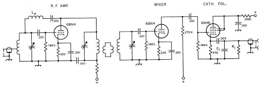
Fig. 1. Basic circuit of the 144-Mc. co-iverter discussed by W8WXV. Values of R1 and Ci depend on the intermediate frequency used and the sensitivity of the receiver to which the converter is connected.
A later model used only 6BN4s throughout, including two of them as crystal oscillator (38.333 MHz crystal) and tripler to 118 MHz. This converter has an i.f. of 26 to 30 MHz, to allow full band coverage with the 75A-3.
Adjusting the neutralizing coil in such a stage is usually a stumbling block for the v.h.f. converter builder. A noise generator is not needed here. Remove the plate voltage from the r.f. stage, and adjust the inductance of the neutralizing coil for minimum feedthrough on a strong signal. This method dates from the adjustment of neutrodyne broadcast receivers in the '20s, but it has been little used of late, probably because a minimum is not readily checked by listening methods. A visual indication can be obtained as follows: connect a vacuum-tube voltmeter at the mixer grid; then, with the transmitter running and its signal tuned in, adjust the inductance of LN for minimum indication. To prevent feed-back troubles, the coil is mounted above the chassis, on small feed-through insulators.
Many converter designs neglect the possibility of damaging r.f. amplifier tubes due to excessive grid-current flow when the transmitter is operating. The blocking capacitor and grid leak shown in Fig. 1 take care of this.
Is the noise generator infallible?
When a noise generator is used the best point for connecting the r.f. input seems to be nearly halfway up the coil. However, it is the writer's contention that the best way to make input circuit adjustments is with a very weak signal coming in on the antenna with which the converter is to be used. It is recognized that there must be overcoupling to the input circuit, but just what this mismatch is could be anyone's guess. When you are receiving, the receiver input circuit is the load on the antenna line. If this load has been adjusted for optimum noise figure with a noise generator, it may be badly mismatched for the antenna. This could cause high standing-wave ratio and consequently excessive losses in the line. It could also cause a bad mismatch at the antenna, if the s.w.r. is high and the line was a critically " wrong" length. Thus we could have a good noise figure, but poor reception.(1)
This possibility can be avoided by making signal-to-noise ratio tests with the antenna on. This is not easy, especially if the receiver with which the converter is used is highly selective. The signal must be constant in level (no weak DX or signal off the side of the beam is likely to be) and it must be tuned on-the-nose at all times. A very weak signal generated down the street is useful for this purpose, but be sure that it is being picked up by the antenna, not by the converter circuitry, or through power leads.
Tuning of the input circuit, the position of the tap, and even the antenna line length, can then be varied for best signal-to-noise ratio. Don't adjust for maximum signal strength. Be sure that maximum rise in signal over noise is the end result of the tinkering process.
The noise generator is a very useful device. It can give you a quick check on tubes, and it is probably close to optimum for adjustment purposes, but careful signal-to-noise ratio tests under actual receiving conditions are the only certain evidence of optimum receiver performance.
Controlling lf output level
Particularly if the receiver is to be used for work on other bands, it is nice to be able to set the converter output level so that the receiver S meter works normally in both classes of service. This is often taken care of with an i.f. amplifier stage, but the gain such a stage affords is not needed with most modern receivers. A cathode follower is a simple and effective means of coupling between the mixer and the receiver input circuit, but conventional gain-control methods are not applicable to cathode followers.
The i.f. output circuit shown here does not provide a variable gain control, but the value of either the load resistor, R1, or the by-pass capacitor, C1, can be adjusted to suit the receiver in question. The values used at W8WXV will require modification for other intermediate .frequencies, and possibly for other receivers. We tune only the first megacycle of the band with the converter shown in the diagram, using an intermediate frequency of 1.5 to 2.5 MHz on a 75A-3. Mixer output is relatively high with this low i.f., and the value for R1 turned out to be only 0.2 ohm. At this i.f. a bypass of 2 nF keeps the 144 MHz energy in the mixer output from being passed on to the receiver, but does not drop the i.f. level seriously. With a higher i.f., the bypass would have to be a lower value, and the resistor probably higher.
With a given value of bypass, the load resistor should be adjusted so that the noise from the converter just overrides the receiver noise. A basic point of v.h.f. receiver performance, often not fully understood, should be restated here. The signal-to-noise ratio of a receiving setup that is working properly will be determined entirely by the first stage in the converter. There is, therefore, nothing lost in cutting down the gain of the over-all setup by loading down the mixer output in the manner described above, provided the communications receiver still tracks properly. The only difference these load resistor changes make is in the reading of the S meter on noise. This should be set so that noise with the antenna connected just begins to show on the meter - if you are lucky enough to live in a spot having little or no man-made noise.
With an i.f. of 26 to 30 MHz, the above method of controlling the overall gain was not satisfactory. Using normal bias and by-passing and loading to reduce the gain upset the input circuit of the 75A-3, so that it would not track properly. The gain of the converter was then adjusted by varying the bias resistor of the cathode follower. A value of 7500 ohms gave about the right output level with the converter using all 6BN4s.
Notes
- An interesting point is raised here. Whether or not the author's statement is true would seem to depend on two factors, neither of which can be readily determined in most amateur receiving setups for the v.h.f. bands. First is the degree of mismatch introduced in adjusting for optimum noise figure with a noise generator. If the mismatch is considerable, his idea is undoubtedly correct. And if the mismatch between antenna and line was appreciable in the first place, it is anyone's guess as to the degree of mismatch under actual receiving conditions. A cross check under actual receiving conditions is a worthy effort, in any case. - Ed.
Allen R. Burson, W8WXV.