Keeping equipment cool
Heat disposal in low- and medium-powered electronic assemblies.
There was a time when the problem of eliminating excess heat in amateur equipment was rarely given any consideration. Layouts were generous with space, enclosures were rare, and operation was intermittent enough so that high operating temperatures were only occasionally responsible for component failures. Not so today, what with the necessity for good shielding. As this article shows, there is a great deal more to effective heat disposal than simply adding a fan.
Whenever the power input to an electronic device exceeds the power output, the "lost energy" must be disposed of somehow, usually as heat. As no electronic device is 100 per cent efficient, the problem of heat disposal is always with us.
Most engineering texts on heat disposal are too involved and theoretical to be of much use in solving practical problems. The majority of practical works, of which there are many, give rather good empirical data for installations involving kilowatts and megawatts, but are strangely silent regarding the problem of keeping an assembly 17 by 8 by 10 inches, with an internal dissipation of 55 watts, at a temperature below 180 degrees F.
Practical heat disposal may be divided very roughly into four broad categories, which are somewhat interrelated and overlapping. Any improvement in one category will usually result in some improvement in at least one of the others. These categories are:
- Over-all heat reduction.
- Localized heat reduction.
- Localized thermal stabilization.
- Heat exclusion.
The primary aim in over-all heat reduction is to make an assembly that will run cooler. To have a minimum of heating in any assembly, keep the power input to a minimum, and use the most efficient circuits possible. Don't overload any component, for the heat output of most electrical devices increases faster than the useful power output after the optimum operating point is passed.
Electrical efficiency
Use of efficient components suggests employment of selenium or silicon power rectifiers in place of tubes; LC rather than RC filters; semiconductor diodes in place of thermionic diodes; minimum-drain bleeder resistors; low-drain voltage regulators; capacitative, rather than resistive, a.c. voltage dividers; and even use of high-voltage filaments in some cases. Operation of tubes at minimum practicable voltages (such as 150 in place of 300) reduces not only heat production but also power-supply requirements.
To cite only one way in which heat production can be reduced in an electronic assembly, let us take the case of a power supply using a 5U4 rectifier. Heat production here will be 15 watts from the filament, up to 4 watts plate loss, and a minimum of 1 watt core and copper loss in the transformer - totaling about 20 watts. If we substitute selenium rectifiers, heat production will promptly drop to about 5 watts, because we have eliminated the filament heat from the assembly entirely. Selenium rectifiers are both bulky and costly, particularly in the higher voltage ranges, but produce much less heat in operation than a thermionic rectifier. If we now replace the selenium rectifiers by silicon rectifiers in appropriate voltage range, the four watts of plate loss produced in the original 5U4, or its equivalent produced in the selenium rectifiers, drops to about 0.5 watt, because of the very low voltage drop in silicon rectifiers. We have also raised the output voltage of the rectifier-filter system for the same reason, and the total heat production from the power rectifier and transformer is now in the neighborhood of 1.5 watts, or about 7 per cent of what it was at first.
Chassis
Use of a conductive chassis, with as large a surface area as possible, will facilitate equalization of internal heat and rapid cooling by conduction - aided by convection in most instances - as well as by radiation, which occurs at the surfaces of all components and over all parts of the chassis. Most rapid conduction will occur with a copper chassis, but steel, which also furnishes magnetic shielding . and mechanical rigidity, is usually the optimum material. Aluminum, although a fairly good conductor of heat, has somewhat unhappy mechanical properties for many applications.
Use of chassis brackets not only increases mechanical strength but also adds to the surface area of the chassis, facilitating cooling by radiation and convection, provided there is a conductive bond between the chassis and the end brackets. In general, if the bond between chassis and brackets is a good electrical conductor it will be a good thermal conductor also.
Air Vents
Last, but by no means least, adequate vents for convectional air circulation, and hence convectional cooling, must be provided. If an electronic assembly is completely boxed in so that convection cooling does not take place or is sharply restricted, cooling will occur only by heat conduction to the enclosure, and thence by radiation from it. As the thermal conductive path to the enclosure may be of high resistance, and since the trapped air between the assembly and the enclosure is a poor conductor of heat, the assembly will tend to operate at a very high equilibrium temperature.
If adequate paths for convective cooling are provided, as by inlet and outlet vents with an uninterrupted air path between, convective cooling will take place automatically, appreciably lowering the equilibrium temperature.
Arrangement of air vents in a medium power assembly - a 10-tube, six-band monitor receiver which consumes 65 watts - is shown in Fig. 1. Upper-level vents permit heated and expanded air to escape, lower vents allow cooler air from the environment to enter. Rubber feet on the case bottom keep the bottom vent unobstructed. It is important that both top and bottom vents be provided. If the lower vents are omitted convection will not take place, because there is no inlet for cooler "replacement" air. Remember that a chimney will not draw if the stove draft is closed!
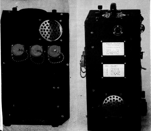
Fig. 1. Air vents to permit convective cooling of a monitor receiver.
Venting arrangements for a smaller assembly, dissipating only about six watts but somewhat temperature sensitive, are shown in Fig. 2. A similar vent is provided in the chassis itself, to permit "through" air circulation.
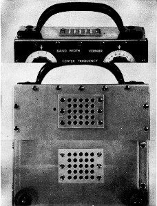
Fig. 2. Vents in small electronic device to facilitate convectional cooling. A similar vent is provided in the chassis shelf, inside the case, to provide an "open" air channel.
Vent apertures should also be provided in the tops of chassis and other "inverted box" structures to prevent entrapment of heated air. Unless these are provided, localized "hot spots" may occur under the chassis, leading to seemingly mysterious failures of components even though the entire assembly operates at an average temperature far below the maximum for the specific items.
Local heat reduction
Localized heat reduction is desirable or necessary in most electronic assemblies because some components will operate indefinitely at relatively high temperatures but others will fail promptly if heated to much lesser values. For example, ceramic-insulated fixed resistors will operate satisfactorily above the melting point of soft solder, while tube bases come loose at about 150 degrees C.; and electrolytic capacitors, in general, imitate Vesuvius at temperatures somewhat below 90 degrees C.
The general method of localized heat reduction is to prevent heat from normal "stoves" from reaching temperature-sensitive components. This is accomplished by use of heat baffles, guided convection, and insulation. One example of thermal shielding, to prevent cooking of dry electrolytic capacitors by tube heat, is shown in Fig. 3. Here, a high-power pulse amplifier tube, which dissipates considerable power, is surrounded by a tubular shield. This reflects back much radiant heat and acts as a chimney to expedite convectional cooling. Note that the bottom of the cylindrical shield is open so it will "draw." Between the power rectifier, at left, and the capacitors is a vertical plane baffle which reflects back heat from the rectifier and guides local convections up both its surfaces. As these baffles function principally as reflectors, their surfaces should be bright. Without these heat baffles capacitor life was measurable in hours of operation, and not many hours at that. With the baffles in place, the operating life of the capacitors was extended to years, so that the equipment became obsolete before they failed.
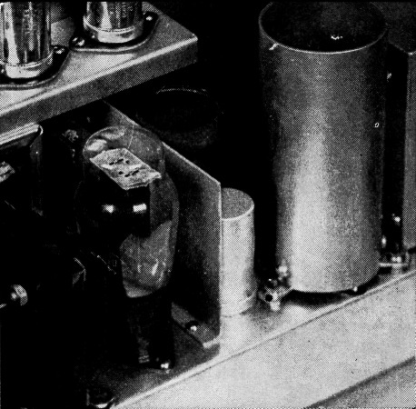
Fig. 3. Thermal shielding in a pulse amplifier.
Another installation using baffles to reflect heat away from a capacitor bank, along with chassis vents to keep internal temperatures within reasonable limits, is shown in Fig. 4. Socket mounting of the capacitors here insulates them against heat conducted along the chassis surface.
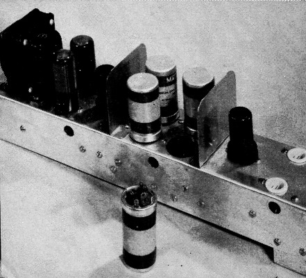
Fig. 4. Use of heat baffles and chassis vents to lower capacitor temperatures and keep internal chassis temperature down.
Temperatures of many components, such as resistors, can be lowered by use of oversize components. If a 1-watt resistor is electrically necessary and the assembly runs hot, substitution of a 2-watt resistor will sometimes be helpful. This lower temperature is not due to lower dissipation. If the resistor dissipates one watt, it will do so regardless of its nameplate rating, but a higher-rated resistor is physically larger and has a larger radiating surface, so its equilibrium temperature will tend to be lower.
Mounting of tubular elements, such as resistors, with through bolts and massive brackets will facilitate conduction of heat from the component to the chassis. Again, this will not reduce the amount of heat produced, but will conduct it away from the source more rapidly, lowering the equilibrium temperature.
Rectifiers
Selenium rectifiers in most amateur and some commercial equipment are operated somewhere between maximum recommended current and the "stink point." In addition, they are commonly stuck in an unvented corner of the chassis - creating, so far as the rectifier is concerned, a sort of autocrematorium, as in Fig. 5, lower left.
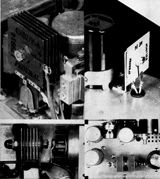
Fig. 5. Selenium rectifier mountings.
Much of this trouble can be eliminated by use of adequately sized rectifiers, or even oversized rectifiers (more radiating area for the wattage to be dissipated); and by mounting them above chassis, as in Fig. 5, upper left and right. Use of a through bolt and heat conductive bracket will be found helpful in eliminating unwanted heat. A pair of small selenium rectifiers mounted in this manner is shown in Fig. 5, lower right.
Perhaps the most satisfactory mounting for the smaller selenium rectifiers is by bracketing them over a relatively large chassis hole, as in Fig. 6. Here convectional cooling is at a maximum, conduction cooling is facilitated by the center bolt and brackets, and wiring to the lugs is made easy since they project below the chassis top even though the body of the rectifier is above it.
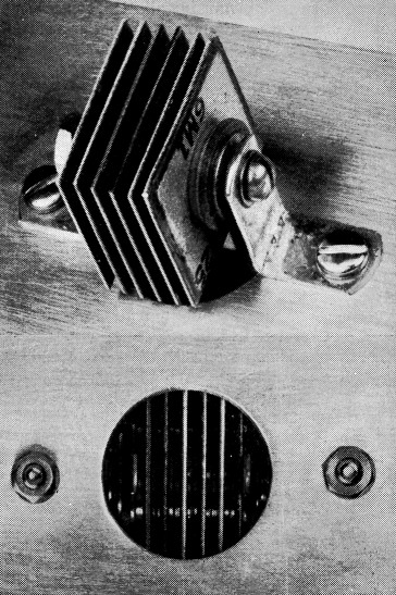
Fig. 6. Recommended mounting for selenium rectifiers.
Power Tubes
By use of suitably vented sockets, a large power tube can be made to drive convections that will ventilate a large part of an electronic assembly. By mounting a standard socket in a vented sunk assembly, as in Fig. 7, air from under the chassis will be sucked out and upward by the convection about the power tube, provided a cool air inlet is also present under the chassis. This particular vented sunk assembly, heavily chromium plated and quite "professional looking," is found in most plumbing shops where it is usually called a sink strainer.
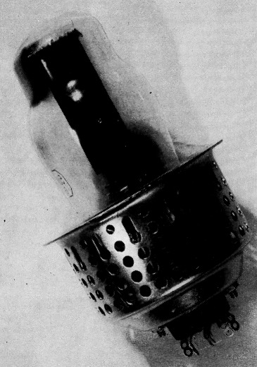
Fig. 7. Vented sunk socket mounting for power rectifier.
Careful arrangement of components will often remove most of the problems of heat disposal without the use of complicated or costly special devices. One example of this is shown in Fig. 8, where the major heat producers, the power rectifiers (A) are surrounded by the transformers and chokes of the power supply, which are substantially heat-immune. A heat baffle (B) is placed between the audio power tubes and the nearest electrolytic capacitor, to prevent cooking it. Capacitors are protected against heat from the two adjacent 12AU7s by wide spacing (C). Convectional cooling of both the chassis shown and of chassis above and below it is assisted by leaving the speaker well (D) open at both top and bottom.
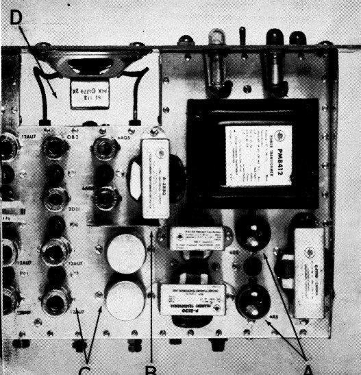
Fig. 8. Component arrangement to minimize heat disposal problems.
Thermal stabilization
Localized thermal stabilization is necessary or desirable when frequency is controlled by heat-sensitive components, which includes almost all components except zero temperature coefficient crystals. One of the best methods yet developed involves the use of insulated compartments with the temperature controlled thermostatically. This is substantially a crystal oven, for which many adequate designs are known.
Additional thermal stabilization can be provided by mounting the temperature-sensitive device on or in a block of some substance with great thermal mass, such as an iron or brass block. If the temperature-control device, such as a thermostat, is mounted on the surface of this block and the thermally sensitive equipment (such as a crystal) within it, internal temperature variations can be held to a very small fraction of those at the thermostat.
By use of "thermal ballast," plus shielded and insulated containers, plus a sensitive thermostat or series of them, the temperature at the critical point can be held constant to any accuracy desired (except 100 per cent!) and stabilities of plus or minus 0.01 degree C. are rather easily attained.
Where lesser temperature stability is needed, as in most amateur and commercial equipment, thermal stabilization is commonly obtained and maintained by leaving the equipment turned on at all times. If the installation as a whole is fairly massive, rather gratifying thermal stability can be attained in this manner.
Isolation
Thermal isolation of a heat-producing component, so that its heat will not affect adjacent components and so that the heat produced by adjacent components has little effect on its equilibrium temperature, is attained by use of basal insulation and concentric lateral shields, vented to facilitate convection, as in Fig. 9. At the extreme left is the entire shield assembly.
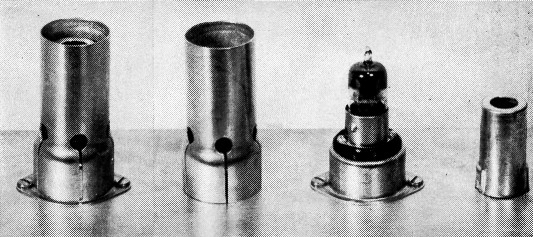
Fig. 9. Thermal isolation of a heat-producing element.
To its right is the outer "chimney," vented to allow influx of cooler air at the bottom. Next is the tube, mounted in an elevated and insulated socket, to reduce conduction of heat to and from the main chassis. At extreme right is the tube shield, an entirely conventional component.
Tests with nested shields of this type show that, for a tube dissipating about five watts, the spacing between the tube shield and the outer chimney must be at least 1/8 inch, and full convectional cooling does not take place until the spacing is about ¼ inch. All other factors remaining the same, tube temperature changes with this type of shielding are slightly less than one fifth the changes without the shielding. An additional concentric shield improves the thermal stability only by a factor of about 1.5, and a fourth shield causes such a small improvement that it might well be omitted.
Fans
Both localized and general cooling can be facilitated by use of fans, although the improvement that they can bring about is not always as great as is commonly believed. Fan motors, particularly the midget shaded-pole jobs that are quite popular, produce considerable heat themselves. Only if the fan removes more watts of heat than it produces will its use lead to improved cooling.
Placement of fans and proper direction of their air flow is quite important. A very small fan directed to aid convection may be a very effective cooler, but the same fan opposing convection may be less useful than no fan at all. Also, for any given installation, there is an optimum rate of air flow. Up to this point, increasing the air flow increases the cooling in almost any direct ratio. Beyond this point, doubling the air flow may only increase the cooling 20 per cent. In very general terms, subject to many exceptions, optimum cooling is to be expected when the air in a chassis enclosure is changed from five to ten times a minutes.
Small fans are best driven by shadedpole induction motors; larger fans by capacitor start and run induction motors. Brush-type universal motors are not recommended for use around communications equipment, as very extensive shielding and isolation are needed to keep the brush noise out of receiving equipment. Where relatively large amounts of heat must be dissipated, as in high-power transmitters, it is commonly desirable to mount the fan motors outside the chassis enclosure, and also out of the air stream, so that fan-motor heat is not carried through the electronic assembly. Centrifugal fans are ideal for this specific application.
In considering all heat disposal problems, both economics and good sense should limit our efforts to getting rid of harmful heat. Little or nothing is gained by running equipment at 5 degrees above ambient when all components are substantially immortal at 25 degrees above ambient. Improvement of performance and service life will result from keeping the over-all equilibrium temperature somewhat below the maximum rating for the components used, and frequency stability will be improved by minimizing changes in the equilibrium temperatures of the frequency-determining components. Further heat reduction is usually supererogatory, like measuring bricks with a micrometer, and gives little useful return for the effort expended.
General rules for heat control can be summarized as follows:
- For minimum heating of a given assembly, keep power input at a minimum.
- Use components and circuitry of maximum electrical efficiency. All input energy that does not appear at the output is dissipated as heat.
- Arrange components and circuitry for minimum heat at critical points. Wherever possible, isolate heat-sensitive components from heat sources by interposing a heat-immune component. Remember that radiant heat follows the inverse square law; that heat conduction is substantially a linear phenomenon; and that heated convective air rises.
- Arrange extra heat conductors, vents, baffles and cooling fans to compensate, insofar as possible, for remaining uncorrected thermal conditions.
- Apply Occam's Razor to each and every planned layout and circuit. This useful logical tool can be paraphrased into the question, "Is this the simplest arrangement that will perform the requisite function?"
- Build and test.
- Make necessary corrections in installation.
Acknowledgment
The writer is indebted to Mr. James P. Welsh of Cornell Aeronautical Laboratory, and to Dr. Stuart W. Grinnell of Stanford University, for helpful discussions of thermodynamic problems related to heat control and disposal; and to Mr. John Bethel of Palo Alto, Calif., for skilled photographic work.
Ronald L. Ives.