80 meter loading without harmonics
Keeping spurious signals from being radiated.
If you're using a coax fed antenna, be it dipole, trap, or vertical, here is an antenna coupler that will work in coax B line. This gadget will help you load your transmitter and even more important, keep your 80-meter second harmonic at home where it won't earn you FCC notices!
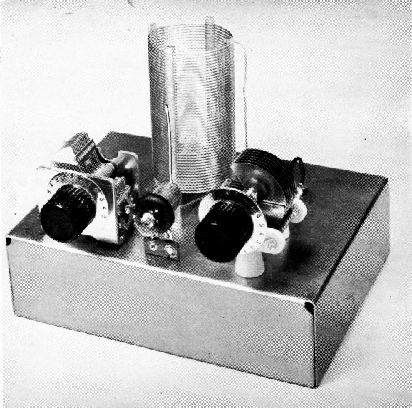
An 80-meter antenna coupler like this is easy to build and tune, and assures that the transmitter can be loaded fully and that harmonic radiation is suppressed.
The neon bulb between the two capacitors serves as a tuning indicator; it is coupled to the coil through the capacitance between the coil and the upright length of wire. Phono jacks mounted 4 inches apart at the rear of the chassis are used for input and output connections. The lefthand capacitor, C1, is mounted directly on the chassis, but C2, at the right, is supported by small ceramic insulators.
Recentley at a radio club the author asked how many of the Novices present had received "QSL cards" for harmonics from the FCC. Of those present, approximately half had been cited by the FCC! All of the notices were for second harmonics of 80-meter operation. The unhappy part of the situation is that simple preventive measures would have kept the harmonics from being radiated. Before we discuss methods for preventing harmonic radiation let's first see what a harmonic is and how it can cause trouble.
Harmonics, harmonics, harmonics
When you key your transmitter on, say, 3725 kc., you want all your output power to be on that one frequency. Unfortunately, life isn't that simple. Transmitters have the nasty habit of generating additional signals at integral multiples of the fundamental. These signals are called "harmonics." If the fundamental is 3725 kc., there will also be a weaker signal at 7450 kc., a still weaker one at 11,175 kc., another at 14,900 kc., and so on up. As a Novice you may not know all of the amateur band frequency limits but, take our word for it, the harmonics just listed do not fall in any amateur band. It is bad enough to cause unnecessary interference to fellow amateurs, but you can be sure the commercial services take a very dim view of amateur interference to their signals. The transmitter is determined to generate harmonics, but the harmonics will generally not be radiated if we can keep them from reaching the antenna.
The first step in cleaning up a harmonic problem is to find out how bad the harmonic is. This can be determined quickly with the help of a neighboring ham by having him listen at the harmonic frequency. He should be at least a couple of miles away from you, otherwise your fundamental signal may overload his receiver. An overloaded receiver can generate harmonics and "birdies" in itself. This would, of course, lead to false conclusions by your friend.
If you find that your friend can copy a harmonic of your fundamental, you must do something to eliminate the harmonic, no matter how weak it is. Otherwise, it will be just a matter of time before you receive an official notice from the FCC.
Possibly you don't have any amateurs living nearby who can check your signal. In that case there is another way to determine if harmonics are reaching your antenna. Build yourself a simple absorption-type wavemeter. The one described in July QST(1) is sensitive enough for checking harmonics.
To use the wavemeter to see if harmonics are getting to the antenna the instrument should be coupled to the output lead in the transmitter (or to the feed line if Twin-lead or open-wire feeders are used). Then tune the wavemeter through the harmonic frequencies. If even a trace of harmonic shows it must be suppressed.
The wavemeter will also show if your transmitter is tuned to the correct band. It is possible with many transmitters to tune them up on the wrong frequency. If you want to tune up on 3725 kc. but actually end up on 7450 kc., it is just as bad if not worse than having a harmonic. That's why it is a good idea to have a wavemeter to check the tuning of your rig.
One way to reduce harmonics to a point where they should no longer be a problem is to install an antenna coupler in the feedline. Fig. 1 is the circuit diagram for a coupler to be used with coax feedlines. Most transmitters these days are designed to be worked into coax lines. Unfortunately, if you go direct from the transmitter to the antenna without benefit of a coupler (or filter), it is quite easy to end up with an appreciable amount of harmonic being radiated. The coupler described here, when installed in the coax line near the rig and correctly adjusted, will provide adequate harmonic attenuation. Some transmitters have no means for adjusting the coupling or loading of the final amplifier. Another advantage in using this coupler is that it will provide such an adjustment.
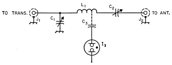
Fig. 1. The circuit for the simple coupler for coax feedlines.
Making the coupler
The coupler shown here is mounted on a 2 × 5 × 7 inch aluminum chassis. Two phono jacks mounted on the back of the chassis are used for J1 and J2. The leads from the jacks are brought up to the top of the chassis through two holes in the chassis top. Rubber grommets are used in the holes to provide further insulation for the wires.
Both variable capacitors, C1 and C2 are mounted on top of the chassis. Standoff insulators are used for mounting C2 because this capacitor must be insulated from the chassis. The coil L1 is made from a length of Miniductor stock by unwinding fifteen turns from one end and a single turn from the other. When the fifteen turns are unwound, four polystyrene support bars approximately one inch long remain. The coil is mounted on the chassis by cementing the ends of the bars to the chassis with Duco cement. Let the cement dry overnight and the coil will be firmly mounted on the chassis.
An NE-21 neon bulb, mounted permanently on the coupler chassis, is used for an output indicator. A ½ inch diameter grommet is slipped over the glass bulb and a piece of stiff wire is wrapped around the grommet. The wire is soldered to a standard terminal tie-point mounted on the chassis between the two variable capacitors. A 2½ inch length of hookup wire is soldered to the base tip of the neon bulb. This short length of wire serves as a capacitive pickup, C3, to the coil.
The antenna system
A sketch of a Novice installation using the coupler described here is shown in Fig. 2. The diagram also includes the dimensions of an 80-meter dipole for the Novice band.
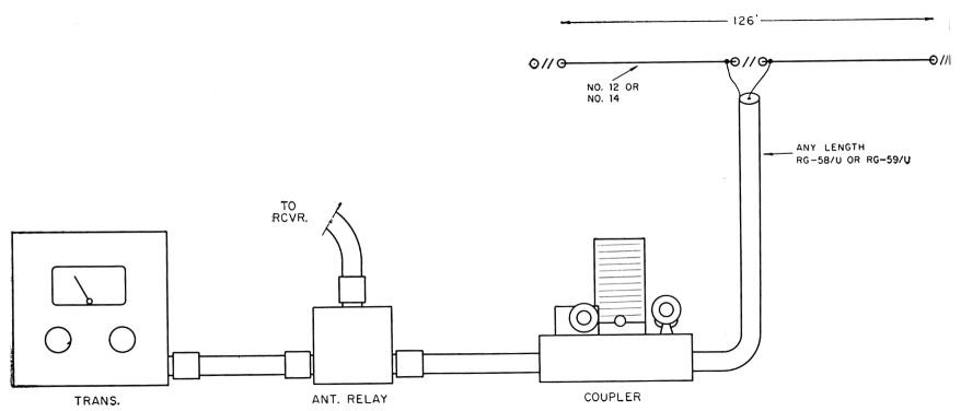
Fig. 2. This drawing shows an antenna system for operation in the 3.7 to 3.75 Mc. Novice band. Either RG-58/U or RG-59/U coaxial cable can be used to connect the different units together. To use the same antenna for receiving, an antenna changeover relay can be installed as shown or, if desired, it can be mounted inside the transmitter.
The coupler can be installed anywhere in the station but it is usually more convenient to mount it near the transmitter. An antenna change-over relay or switch can be installed at the transmitter or in the coax line between the rig and the coupler.
In order to "get out" well the antenna should be mounted as high above ground and as clear of surrounding objects as possible. The antenna will still work if it isn't mounted high and clear but don't expect to get as good results. Some amateurs don't have the necessary space to put up an antenna 126 feet long. In such a case the ends of the antenna can be bent down or to one side to fit a shorter run.
The feedline can be any convenient length, and one of the advantages of coax is that it can be run along metal rain gutters, through pipes, and even under ground without upsetting the electrical characteristics of the line. However, if possible, it should be perpendicular to the antenna for the first 50 feet or so from the antenna.
Adjusting the coupler
There is nothing complicated about adjusting the coupler, assuming the feedline and antenna are reasonably well matched, but certain precautions should be observed to obtain maximum harmonic attenuation. Turn C1 to maximum capacity (plates fully meshed) and leave it set at that position. Now turn on your rig and tune it up normally, dipping the final to resonance. Next, tune C2 for maximum brilliance of the neon bulb. If the bulb doesn't light move the pickup wire closer to Li; if the light seems too bright move the wire away or make it shorter.
You may find that there are two settings of C2 that will cause the bulb to light. One will be near maximum capacity and the other near or at minimum capacity. It is very important to use the setting of C2 nearest maximum capacity (plates fully meshed) as this is correct tuning for 80 meters. A tuning indication near minimum occurs when the antenna coupler is tuned to the second harmonic and this is exactly what you do not want to do.
To increase the loading of the amplifier stage in the transmitter decrease the capacity of C1. Once you have obtained the recommended plate current reading, with the amplifier tuned for a dip, the transmitter is adjusted.
Some amateurs have antenna systems using 300-ohm Twin-Lead for a feed line. The usual custom with this type of installation is to come out of the transmitter with coax to a set of balun coils and then use 300-ohm line to the antenna. Unfortunately, balun coils do not provide harmonic attenuation so such a system can get you into trouble. The coupler described here can be installed in the coax line between the transmitter and balun and will give you the protection you need.
We have discussed only the problem of 80-meter harmonics since, as pointed out earlier, they are responsible for the majority of FCC tickets to Novices. However, the same techniques outlined here can be used on the other bands. For additional information on antenna couplers and harmonics the reader should refer to The Radio Amateur's Handbook, or to the articles listed below:
- McCoy, "The evils of multiband antenna systems - and the cure," QST, Mar., 1957.
- McCoy, "Eliminating 80 meter novice harmonics," QST, Mar., 1956.
- Wood, "What about low frequency harmonics?" QST, August, 1955.
Notes
Lewis G. McCoy, W1ICP.