Filtering and shielding the station receiver
Measures for reducing stray pickup and radiation.
Worthwhile benefits result from good shielding and filtering in a ham-band receiver - for example, two not specifically mentioned by the author are better receiver utilization of the directive characteristics of beam antennas and greater immunity from II noise pickup when the transmitting antenna is used for receiving. The simple measures described here can be applied in principle to practically any receiver that needs treatment.
The average amateur purchases a commercially-built receiver as part of his station. Commonly he will find that the receiver, while generally satisfactory and meeting all advertised specifications, has some undesirable features. Two faults often found in receivers are unsuitability for rapid break-in operation and the production of television interference particularly when receiving 10-, 15-, and 20-meter signals. This note tells how these troubles were eliminated from my HQ-129X and - in general - the methods by which they would be minimized in any receiver.
Difficulties with break-in receiver operation are usually caused by excess transmitter signal leaking into the receiver, making it necessary for the receiver send-receive switch to be turned on and off for each transmission. This often causes a frequency drift making the receiver lose the incoming signal temporarily if the receiver is adjusted for greatest selectivity. Other very undesirable results of transmitter signal leaking into the receiver are overloading of the first stage, shortening the life of the tube nearest the antenna, and occasionally burning out of the first tuned circuit. Similarly, overload of the first grid will cause pulses of grid current to flow, generating transmitter harmonics in the receiver for transmission to nearby television receivers. This will occur even if the receiver send-receive switch cuts off the plate and screen voltages of the first tube, for only the cathode and control grid of the first (or other) stages are involved in this type of harmonic generation. If the transmitter signal can be kept out of the receiver, none of these troubles will occur.
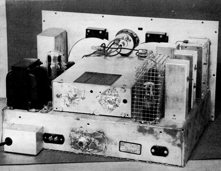
Shielding of sensitive pick-up points in the author's HQ-129X utilized common materials such as hardware cloth and aluminum foil. The small box at the lower left houses the a.c. line filter. Not visible is the additional internal bypassing on leads to exposed parts such as the pilot lights.
Modern receivers are all potential transmitters. This is a characteristic of superheterodyne receivers, for this type includes an oscillator whose output frequency has a fixed difference with a desired incoming signal. All oscillators have some harmonic output, and if the receiver oscillator is not sufficiently shielded and filtered (like a good ham transmitter), it may radiate enough harmonic power to interfere with television receivers. Harmonic radiation is not a fault of just amateur receivers, for most oldtimers remember how whole sections of the 160-meter band were made unusable by fundamental and harmonic radiation from a.c.-d.c. broadcast receivers.
Curing one of these troubles will usually cure the other, for the filtering and shielding necessary to prevent the transmitter signal from entering the receiver will also effectively block receiver oscillator harmonics attempting to leave the receiver.
Extra advantages result from receiver filtering and shielding that is effective enough to make the receiver antenna connection the only r.f. path into or out of the receiver. Antenna line filters become effective against strong unwanted stations. The receiver is always left in RECEIVE position(1) with improved receiver stability. A transmission-line t.r. switch(2) has a chance to be really effective, and even an antenna duplexing bridge can be used.(3)
Working Over the HQ-129X
Three local hams had TVI trouble with their communications receivers (all nationally-known, factory-built) and I wanted to try antenna duplexing bridge experiments. As my receiver had already been torn into for other modifications, it was selected for the full treatment. Many of the modifications incorporated will not be necessary with other receivers of even the same model, but severe test conditions were set up so that every possible type of signal leakage would occur.
The receiver was tested with a shielded resistor dummy antenna, the resistor matching the input impedance as determined by diode noise generator measurement(4) The transmitter was loaded into the station antenna for the initial tests. Later, when the pickup had been substantially reduced, the transmitter output was fed into an unshielded series-resonant combination of capacitor, inductor, and resistor (Q of about 11) near the receiver.
The HQ-129X had been modified earlier for use of a low-noise single-ended converter stage,(5) so it is not possible to tell how much pickup the unshielded grid lead of the original 6K8 converter would have had. It is probable there would have been a great deal.
The greatest signal pickup was by the VR-105/0C3 voltage regulator tube used to stabilize the voltage on the oscillator plate and the r.f., converter, and i.f. amplifier screens. It was necessary to shield this tube. An almost equal source of leakage was the 6SS7 r.f. amplifier, because the metal envelope does not provide sufficient shielding against pickup. The shield covering the voltage regulator tube also was extended to cover this r.f. amplifier tube. There is no reason why commercially-available individual shields would not be satisfactory if shimmed with aluminum foil or similar material.
The writer used 3 inch mesh hardware cloth for shielding wherever convenience was not unduly impaired, but recommends the commercial shields when trade-in value is a factor.
The next prominent cause of leakage was the antenna terminal strip. This strip was removed and replaced by an SO-239 coaxial connector soldered in a copper plate which in turn was soldered to the chassis.
| Before | After | |
|---|---|---|
| Receiver connected to shield ed dummy, transmitter on regular antenna | Meter | pegged |
| Shield over VR105/0C3 | Pegged | S9 |
| Shield over 6SS7 r.f. amp. | S9 | S8 |
| Antenna coax connector installed | S8 | S5 |
| Power-line filter installed | S5 | S4 |
| Change to transmitter output into dummy antenna near receiver | S9 | |
| Rear holes in tuning capacitor frame plugged up | S9 | S6 |
| Rear bearings of tuning capacitor covered | S6 | S4 |
| Slot in tuning-capacitor shield covered | S4 | S2 |
| Shield over bottom of chassis | S2 | Less than S1 |
| Leads to meter, pilot lamps and headphones bypassed | Inaudible |
Power-line filters (Sprague Hypass) were next installed in a Bud Mini-Box mounted against the chassis. In the position shown in the photograph the box readily slides through the rear cutout of the receiver cabinet.
The tuning capacitor assembly was the next leaky item. Punched holes in the rear frame were plugged with nuts, bolts, and washers. The slot in the tuning capacitor shield that formerly was used for passing the grid lead to the 6K8 converter was closed by bolting on a metal plate, and the rear bearings of both capacitors were covered with two layers of aluminum foil. The foil was fastened in place with Duco Cement, the centers of the foil layers being insulated from each other and the bearing screw by small pieces of Scotch tape, as shown in Fig. 1.
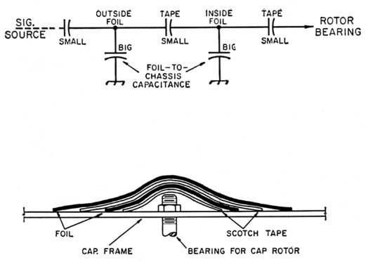
Fig. 1. Method of using foil and Scotch tape to shield the rear bearing of the tuning capacitor. This avoids the necessity for drilling to attach a shield or for soldering the shield to the capacitor frame. The two layers of foil are insulated from each other. Their edges may make contact with the capacitor frame but if not the foil pieces act like a two-section attenuator having the equivalent circuit shown at the top.
Hardware cloth was tacked with solder to the bottom lip of the chassis at one-inch intervals to form a bottom shield. The pilot light, "S" meter, and headphone leads were bypassed with 0.001µf. ceramic capacitors where the leads entered the chassis. It was not necessary to bypass the loudspeaker leads additionally, though this might be necessary in other cases. It likewise may be desirable to bypass the "RELAY" (send-receive) terminals, but the writer has no information since these connections were not used and did not require bypassing.
Altogether, the above measures permitted the writer to be sure that the only signal path to the receiver was through the coaxal connector - where an antenna relay, t.r. box, or duplexing bridge can control the receiver input.
W4SUD's all-purpose 813 amplifier. The output-capacitor switch (coarse loading) is above the turns counter for the variable inductor. Dials near the center are for the plate tank capacitor C4 (above) and the grid tank capacitor C1 (below). To the right of the dials are the controls for the plate padder switch S3 (above) and the grid band switch S1 (below). The toggle switch below the meters is the mode switch 54 with the meter switch Ss to the left. Ventilating holes are drilled in the cover in the area above the tube. The output connector is on the left-hand wall of the shielding box.
Notes
- In the HQ-129X, the send-receive switch controls the r.f., mixer, and first i.f. plate supplies.
- The Wright t.r. switch and many others.
- Fessenden, U. S. Patent 1,170,969 and others.
- Goodman, "How Sensitive Is Your Receiver?", QST, September, 1947.
- Santangelo, "Second Guessing The Experts On The HX-129X," CQ, April, 1952.
David T. Geiser, WA2ANU, EX-W1ZEO.