An all purpose 813 Amplifier
Flexible unit for C.W., A.M., or S.S.B.
In these days, the well-equipped amateur, be he traffic man, DXer or rag chewer, must be prepared for c.w., conventional a.m. and s.s.b. In the 813 amplifier shown in the photographs, provision has been made for convenient changing from one mode to another as well as to any of the bands from 80 through 10 meters.
The circuit is shown in Fig. 1. A turret-type grid circuit is used and the output circuit is a pi network designed to work into coax cable. The inductor is the rotary-type variable. Provision for neutralizing is included. R1 is a parasitic uppressor.
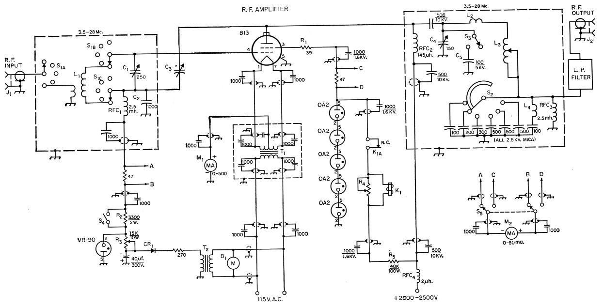
Fig. 1.
| B1 | Ventilating blower, 100 c.f.m. (surplus). |
| C1 | 250 pF variable (Hammarlund MC-250-M). |
| C2 | 1000 pF mica. |
| C3 | Neutralizing capacitor, 10 pF maximum (Johnson 159-250). |
| C4 | 150 pF 6000 volt variable (Johnson 153-12). |
| C5 | 100 pF 5000 volt fixed capacitor (surplus vacuum, Amperex VC-100, or two 200 pF 5000 volt micas in series). |
| CR1 | 130 volt 50 mA selenium rectifier. |
| J1,J2 | Coaxial receptacle (S0-239). |
| K1 | Screen overload relay, 2500 ohms, 7 mA (Potter & Brumfield KCP5). |
| L1 | 3.5 Mc. 32 turns No 20, 1 inch diam., 2 inch long, 5 turn link (B&W 3015 or Airdux 816). 7 Mc. 18 turns No 20, ¾ diam., 1_1/8 inch long, 3-turn link (B&W 3011 or Airdux 616). 14 Mc. 10 turns No. 18, 1/4-inch diam., 11/4 inches long, 2-turn link (B&W 3006 or Airdux 508). 21 Mc. 7 turns No. 18, 3/4-inch diam., 7/s inch long, 1-turn link (B&W 3006 or Airdux 508). 28 Mc. 5 turns No. 18, 3's-inch diam., 5/s inch long, 1-turn link (B&W 3006 or Airdux 508). |
| L2 | 3 turns 3/16 inch copper tubing, 1 inch diam., 1¾ inches long. |
| L3 | 15 µH variable inductor (B&W 3852). |
| L4 | See text. |
| M1,M2 | 3½ inch d.c. milliammeter. |
| R1 | 39 ohms, ½ watt carbon. |
| R2 | 3300 ohms, 2 watts. |
| R3 | 15 kΩ 10 W with slider. |
| R4 | 2 kΩ 4 W variable resitor (Mallory M2MPK). |
| RFC1,RFC3 | 2.5 mH choke (National R-50 or simular). |
| RFC2 | Plate r.f. choke (National R-175-A). |
| RFC4 | V.h.f. choke (National R-60). |
| S1 | Rotary switch: 3 wafers, 3 poles, 11 positions per pole, 5 positions used (Centralab PA-0 wafers, PA-301 index). |
| S2 | Rotary switch: single pole, 10 positions, progressively shorting, 6 positions used (Centralab PA-2042). |
| 53 | Rotary switch: s.p.s.t., ceramic (antenna link switch from BC-375 tuning unit, or Communications Products Model 65). |
| S4 | S.p.s.t. toggle switch. |
| S5 | D.p.d.t. rotary switch (Centralab 1405). |
| T1 | Filament transformer: 10 volts, 5 amp. (Thordarson 21F18). |
| T2 | Bias transformer: 120 volts, 50 mA; 6.3 volts, 2 amp. (Merit P-3045). |
For Class C c.w. or phone operation, 84 is open. The 90 volts of fixed bias, furnished by a small bias supply and regulated by the VR90, is augmented by a drop of about 50 volts across the grid-leak resistor R2 at a normal grid current of 15 ma. This brings the total bias to 140 volts. With 84 closed, the grid leak is short-circuited and the 90 volts of fixed bias alone remains for AB2 s.s.b. operation. (The author also prefers AB2 for c.w. operation because it preserves the keying characteristics of the exciter better than with Class C operation.) R3 should be adjusted so that the VR90 just ignites with no excitation.
Screen voltage is regulated at 750 volts by a string of five 0A2s for s.s.b. operation. When the grid drive is increased for Class C operation, the screen current increases, increasing the drop across the screen resistor R5, and the screen voltage falls to 400. The regulators then lose control and the amplifier is ready for plate-screen modulation.
The screen is protected against excessive input, should the load or plate voltage be removed, by the overload relay K1. The tripping point is set at 40 ma. by the variable shunt resistor R4. One meter, Ml measures cathode current, while the other meter, M2, may be switched to read either grid current or screen current.
Forced-air ventilation is always advisable for a medium- or high-power amplifier if it is buttoned up tight to suppress TVI. A surplus 100 c.f.m. blower does the job more than adequately.
Construction
The amplifier is built on a 13 × 17 × 4 inch aluminum chassis fastened to a standard 12¾ × 19 inch rack panel. The r.f. output portion is enclosed in a 12½ × 13 × 8½ inch box made of aluminum angle and sheet. The VR tubes, relay, blower and meters are mounted external to the box.
The grid tank-circuit components are mounted underneath the chassis and are shielded with a 5 × 7 × 3 inch aluminum box. A standard chassis of these dimensions might be substituted. The bias and filament transformers are in a second box measuring 6 by 3 by 3 inches. This type of construction, together with the use of shielded wire for all power circuits, was followed to reduce TVI to a minimum. Each wire was bypassed at both ends with 0.001 µF ceramic disk capacitors. L4 can be adjusted to series resonate with the 600 pF capacitor at the frequency of the most troublesome channel. A Bud low-pass filter completes the TVI treatment. As a result, the amplifier is completely free of TVI on all channels even in this fringe area.
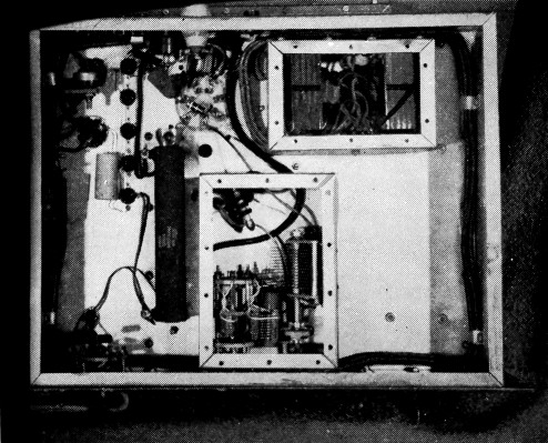
Bottom view of the all-purpose 813 amplifier. The grid tank-circuit components within dashed lines in Fig. 1 are enclosed in the box at lower center. Input links are wound over ground ends of grid coils. Filament and bias transformers are in the second box. The large resistor to the left of the grid box is the screen resistor. The variable resistor in the upper left-hand corner is the relay shunt R4. The selenium bias rectifier is fastened against the lefthand wall of the chassis.
Adjustment
In the pi network, the output capacitors are fixed. However, the adjustment of the network is similar to that of the more conventional arrangement using a variable portion of the output capacitance. The only difference is that the "fine" loading adjustment is done with the variable inductor.
The inductor is fitted with a Groth turns counter, making it easy to return to the proper setting for each band. Until the settings for each band have been found, S2 should be turned so that all of the output capacitance is in circuit. The inductor should be set near maximum for 80, and approximately half maximum for 40. On the higher-frequency bands, the inductor should be set so that the circuit resonates with the tank capacitor near minimum capacitance. Loading should increase as the output capacitance is decreased. A change in output capacitance will require a readjustment of C4 for resonance. When the loading is near the desired point, final adjustment can be made by altering the inductance slightly.
A 20-A or similar exciter is well suited as a driver for this amplifier on all modes. The 813 runs cool at 500 watts input on a.m. and c.w. and at 1000 watts p.e.p. on s.s.b. I believe it is a good compromise between the full legal limit and low cost.
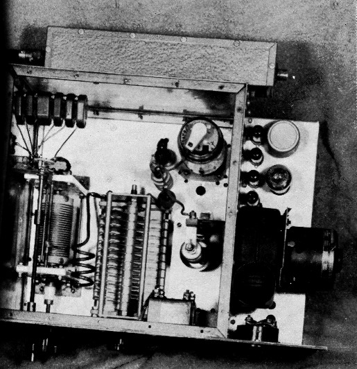
This view shows the placement of components on the chassis. The 813 socket is mounted on spacers over a large clearance hole in the chassis. The several mica output capacitors are assembled in a stack on a threaded rod fastened to the left-hand wall of the shielding box. The neutralizing capacitor and the 80-meter plate padder are to the right of the tank capacitor. To the right of the box are the five 0A2s (the front one hidden), the screen overload relay and the VR90, the blower and meters.
R. A. Thomason, W4SUD.
Screen Protection
Stephen Goch, K2IVB, has pointed out some disadvantages of the screen protective system shown by W4SUD in his circuit on page 36 of the August issue. As K2IVB states, when the contai, of K1 break as a result of overload, the winding of the relay will be de-energized and immediately close again, resulting in a "buzzer" action. It is also pointed out that during the time the relay contacts are open, the 1000 pF capacitor below the relay and the relay are at full d.c. plate potential above ground and should be insulated for at least this value.
One possible remedy for the "buzzer" action would be the substitution of a double-throw relay with a resistor connected between the back contact and ground. This resistor should have a value such that it would draw sufficient current to keep the screen contacts open. The relay contacts would return to normal position removal of plate voltage. - Ed.