A directional coupler for 144 Mc
Reliable S.W.R. measurement at low cost.
With more and more antennas being fed with coax, a reliable means of measuring standing-wave ratio and power in the transmission line is a must if we are to achieve optimum antenna and loading adjustment. This is particularly true at 50 Mc. and higher, yet few of the devices that can be bought or built for these purposes are reliable for v.h.f. service. V.h.f. men who want to be sure that their equipment is working in tip-top order will be interested in the experience of W3GKP reported below.
For some time Bill had been unhappy about the state of the amateur art as regards standing-wave indicators for v.h.f. use. Most of the circuits in the Handbook and other amateur literature are not well suited for use above 30 or 54 Mc. He did not try any of the lumped-constant circuits involving reactive components or potentiometers, because of pessimism regarding the outcome.
Lumped circuits using only resistors, as in the bridge shown in Figs. 21-36, 21-33 and 21-35 in the '56, '57 and '58 editions of the Handbook respectively, can be used at 144 Mc., provided the equipment is built with more attention to v.h.f. requirements than is shown in the Handbook examples. For several years W3GKP used such a bridge, built by and on "permanent loan" from W3GZQ. In this the standard R. is built into a coaxial plug and connected into circuit by a connector of the same type as is used for the unknown. The W3GZQ version is symmetrical electrically and mechanically, and it works much better at 144 Mc. than a 75-ohm model copied from the Handbook.
The standard supplied with it consists of a 47 ohm ½ watt resistor filed to 51 ohms, mounted in a PL-259A plug with the shortest possible leads. As a check W3GKP made another standard, selecting a resistor that matched the original at d.c. and mounting it in the same manner. When these are checked against each other on the bridge, a detectable but negligible reading is obtained. With the aid of laboratory equipment Bill then compared both standards with a General Radio 874-WM 50-ohm termination. With either standard a negligible reading was obtained, demonstrating the worth of the bridge as a device for adjusting antennas. But something that could be driven by the transmitter, and left in the circuit at all times, was desired. This led to an investigation of the directional coupler shown symbolically in Fig. 1.
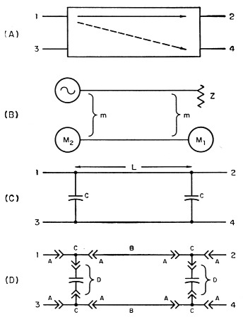
Fig. 1. Development of the 144 Mc. directional coupler. Basic idea of the bridge is shown at A. Mutual coupling, m, between main and side lines, limits directivity (B). Maximum directivity in bridge made of coaxial lines (C) is obtained by introducing coupling capacitances at points so that L is wavelength. Bridge made up from standard coaxial fittings is shown schematically at D.
As seen at A, a directional coupler is a 4-terminal device having the property that most of the power introduced at Arm 1 is delivered to Arm 2, except for a small sample that is delivered to Arm 4. There is no output from Arm 3, unless power is introduced at or reflected from Arms 2 or 4. Such devices can be constructed using lumped circuit elements, coaxial cable, wave-guide, or combinations of these.
A coaxial version might appear as shown at B, which is intended to portray only the inner conductors. Most of the power flows down the main line to the load, Z. A small portion is coupled by m to the side line, and meter M1 gives a reading proportional to the power flowing toward the load. If the main line is terminated properly by Z, M2 will read zero; otherwise it will give a reading proportional to the power reflected by Z. If the generator is a transmitter and Z is an antenna, the ratio of the power readings at M1 and M2 is a measure of the standing-wave ratio, and the difference between the power readings is proportional to the power delivered to the antenna. It should be mentioned that this happy state of affairs results only when Arms 3 and 4 are terminated in matched impedances. This places some special requirements on the indicating devices, M1 and M2.
The ratio of power delivered to Arm 2 to that delivered to Arm 4 is termed the coupling. Due to unavoidable variations in the construction of the device, some power may be delivered to Arm 3, even when Arm 2 is properly matched. The ratio of the power to Arm 4 to that to Arm 3, when Arms 2 and 3 are matched, is termed the directivity. Both the coupling and the directivity may be expressed in decibels. Ideally the directivity should be infinite. Reverting to 1B, the coupling, m, between the main and side lines may be effected at two or more discrete points or distributed over some distance. In addition, it may be inductive, capacitive, resistive, or combinations of these.
Fig. 1-C shows a directional coupler made of coaxial cables, coupled by capacitors, C. If the distance L between coupling points is j wavelength, and the capacitors are equal, the coupler should perform as described. Fig. 1-D shows a fairly practical form, which can be constructed using standard fittings. In this sketch, A are PL259 plugs, B lengths of RG-8/U cable, C M358 T fittings, and D modified PL-258 junctions.
The PL-258 junctions (he used Amphenol 831J) were modified to form a capacitive rather than a direct connection. Examination of one of these will show that its innards are retained by a spring C-ring at one end. If a hacksaw cut is made into the body opposite the gap in the ring, in the plane of the longitudinal axis and at about 45 degrees to the transverse axis, the ring will pop out intact when encountered by the saw blade. The insides can be poured out neatly. If the cut is made into the opening of the C ring, its removal can be effected with a scriber. Parts are the C-ring, two insulating beads and a double female contact. The contact has two flanges near the center, which prevent it from falling out through the holes in the beads. W3GKP cut the contact in half between the flanges, filed the rough ends until he had a smooth flat surface extending over the entire area of the flange, and cemented the two contact pieces back together, with a bit of insulation between.
The smoothing can be done nicely by chucking the contact in a drill press and bringing it down on a flat file. The insulation used was transparent plastic 1/16 inch thick, cut from the lid of a small parts box. This was coated with GC cement, and the assembly clamped lightly in a vise to assure a uniform film thickness. After it dried, the plastic was filed down even with the metal, and the whole assembly coated with cement. It was found that this would stand having a plug inserted, but not removed, so when it is finished the T-fittings should be attached and left on.
On the first attempt W3GKP used RG-8/U cables having a tip-to-tip length of 12% inches when completed. These gave maximum directivity at 121 Mc. The next attempt to hit 144 Mc. was made with cables 10% inches long. For testing, Arm 1 was driven with a General Radio 1021 generator, the attenuator of which was adjusted to a suitable level and left fixed. The output from each of the other arms was measured with the following GR equipment: an 874 20 dB pad for matching, an 874-MR mixer, a 1216 i.f. amplifier, and 1215 oscillator. Relative output was read from the i.f., which is calibrated. The unused arms were terminated in 874-WM 50-ohm loads. Fig. 2 shows how the coupling and directivity varied with frequency.
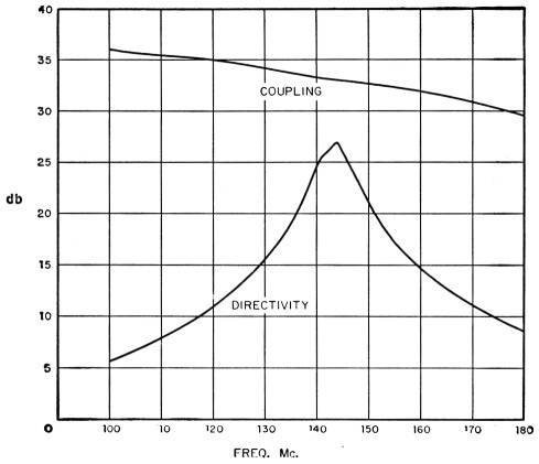
Fig. 2. Coupling and directivity of the 144-Mc. bridge, as measured with laboratory-type equipment by W3GKP.
This looked like a usable device. With a coupling of 33 dB, 1 kilowatt at 144 Mc. in the main line would result in ½ watt in the side line, indicating that the device should be usable with amateur power levels with a simple terminating resistor. Lower coupling might be useful for low-power operation. While best directivity was obtained at or slightly below the low end, it looked good enough over the entire 144-148 Mc. range.
The computed relationship between s.w.r. and apparent directivity for an ideal coupler is shown in Fig. 3. Judging from this, a directivity of 20 db. would result in an s.w.r. error of 1.2:1. By shooting for a null it should be possible to adjust an antenna system to less than 1.5:1. The points indicated by X's in Fig. 3 show the directivity measured for various standing-wave ratios. The 2:1 point was obtained by paralleling two 874-WM units on an 874-T fitting. Ratios of 3:1 and 4:1 were obtained by shunting this with the homemade standards. A single 874-WM was used for 1:1. For 1.2 and 1.25, an open- and short-circuited 874 10 dB pad was used. A plot of the same points, in different form, is shown in Fig. 4, along with the open- and short-circuit points, both of which read well under 1 db. The solid curve is intended to show the variation expected, and it looks as if the coupler favors something under 50 ohms.
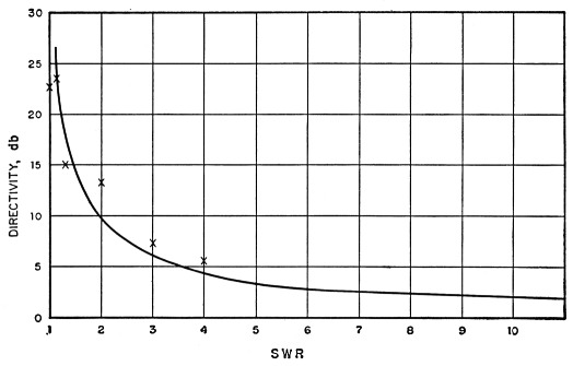
Fig. 3. Computed relationship between s.w.r. and apparent directivity in an ideal coupler. Points indicated by X show measured directivity.
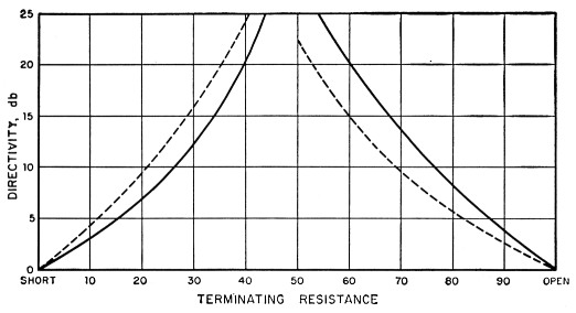
Fig. 4. Directivity for various terminations. Solid line shows expected variation.
The standard resistors used with W3GZQ's bridge were checked, and it was found that his read about 17 db. and Bill's about 22 db. At this point the pin in the plug came loose and broke the resistor lead, so another had to be made. Using the coupler, quite a few resistors were tried. Nominal 47-ohm resistors were consistently better than 33- or 56-ohm units. Most 47-ohm resistors read 20 db. or better.' It was found that the match could be improved by surrounding the resistor with a shield connected to the ground terminal. Using this procedure, another standard was made which read 26.5 db.. which is as good as the coupler. A further check was made with Arm 2 loaded with a Bird wattmeter, a reasonably good termination over the range from 30 to 500 Mc. The directivity was similar to the curve of Fig. 2.
The next step was to construct a voltmeter which would present the proper termination to the side line. The best arrangement evolved to date is shown in Fig. 5. The 500 pF silver-mica capacitor is the smallest physically made by Elmenco. The resistor is selected for best match. Final adjustment was made with the 1N34A crystal diode loaded with the meter, by dressing the 800 pF disk ceramic toward or away from the hot end of the rectifier. Two of these were made which, when checked on Arm 2 of the coupler, showed directivities of 28 and 23 db. Since Arm 4 is more critical than Arm 3, the 28 dB unit is used at Arm 4.

Fig. 5. Schematic diagram and mechanical arrangement of voltmeter.
Figuring that the diode should have a constant load on. it, Bill made up some constant-resistance pads for full-scale ranges of 200, 500 and 1000 microamperes, in addition to the basic 100-microampere range. These were put together in a hurry from standard resistors, and no attempt was made to get the loss just right. The coupler was then driven with the 144-Mc. transmitter, and terminated in the Bird wattmeter. The diode terminating units were attached to Arms 3 and 4.
I Presumably the impedance of the main line is lowered by the coupling capacitors to the point where it works best at 46 ohms or so. This may explain the good luck with 47-ohm resistors. If true, this is an argument for looser coupling, or possibly for use of higher-impedance coax in the main line section. It would not be too difficult to experiment with hand-made coaxial sections having impedances between about 55 and 60 ohms.
The power was varied, and the forward diode was calibrated. Arms 1 and 2 were reversed to calibrate the reverse diode, the resulting curve leaving something to be desired. A step at about 20 watts was due to a change in scale on the wattmeter, and other steps showed up as a result of lack of agreement between the microammeter pads.
Subsequently a proper switch box was made, containing the 100-microampere meter and a group of pads, giving 100, 200, 500, 1000, 2000 and 5000 microamperes full scale. These present constant resistances to both diodes, and are constructed with selected resistors. Duplicate positions are provided for "forward" and "reverse." This was calibrated against the Bird wattmeter, taking care to eliminate the step at 20 watts, by reference to the manufacturer's calibration sheet for this particular meter. Fig. 6 is the result.
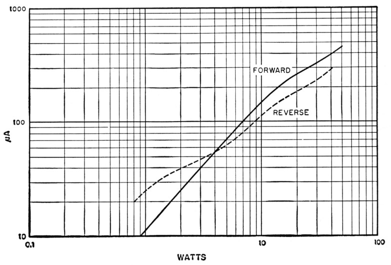
Fig. 6. Forward and reverse calibrations of the final form of the directional coupler.
When the transmitter was fed through the coupler into the station antenna, there resulted currents of 330 microamperes (38 watts) forward, and 30 microamperes (1 watt) reverse, for an indicated directivity of 16 dB, and an s.w.r. of 1.35:1. Using the forward-power indication, adjustments were made on the 829B amplifier, which brought the output from 38 watts up to 55, with an input of 120 watts.
The coupler has been left in the line continuously since it was completed some months ago, and Bill says that he wouldn't know how to get along without it. In rainy weather, for example, when a diode voltmeter on the transmission line gives abnormally high or low readings, the directional coupler indicates only slightly increased forward and reverse power. The net power to the line remains unchanged.