A two-band halo for V.H.F. mobile
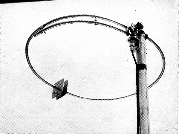
The 2 band halo as it appears when set up for 50 Mc operation. Changing to 144 Mc involves decreasing the plate spacing, by swapping cone insulators, and resetting the gamma matching clip and series capacitor.
50 and 144 Mc. with a single mobile antenna system.
Having thoroughly sold himself on the advanages of horizontal polarization for v.h.f. mobile work,(1) the writer spent many an odd moment pondering the possibility of working both 50 and 144 Mc. with a single antenna system. The need for a two-band antenna was intensified some months ago by a venture into the small sports-car field. There is no room in a car of this type for storing spare antennae!
The 50- and 144 Mc. bands are close to third-harmonic relationship. It should be possible, we reasoned, to work out a method whereby the antenna designed for 50 Mc. could be tunable to 48 Mc. as well, so that it could be made to work on its third harmonic. Tests with a conventional 50-Mc. halo showed that it was not too bad a 144-Mc. antenna, even before any attempt was made to tune it or match it properly. If these two matters could be handled, a halo of 50-Mc. dimensions should make a good radiator on 144 Mc.; probably better than one designed for the higher frequency.
Accordingly, we made up an experimental halo having provision for varying the spacing between the capacitor plates. With a little tinkering as to plate size, it was found that the antenna could be tuned down to 48 Mc. by the simple expedient of changing the spacing of the plates from ¼ to 5/8 inch. This was a natural for two standard sizes of ceramic cone insulators. Next question: could the thing be matched on both bands without a major revision of the feed system?
It would be nice to be able to say that this problem was solved by dreaming up some matching combination that worked on both bands without changes, but such is not the case. Changing from 50 to 144 Mc. with the model shown involves three steps, but they can be handled in a matter of a minute's time. The changeover process may be less than ideal, but it is a big improvement over carrying two halos! Tests in comparison with a standard commercial halo on 50 Mc., and with various forms of dipoles and halos for 144, show that our two-band job acquits itself well on both bands.
Mechanical Details
The halo is made of %6-inch aluminum fuel-line tubing. This material was used because it is both strong and very light, and because we had a stock of it on hand. Any tubing of about %2-inch diameter could be used equally well. The loop is 67 inches in circumference. Again, this was a matter of what happened to be on hand; the coil of tubing lying under the bench happened to be just that big! The capacitor plates are 2h inches square, with the corners rounded off, mainly for the sake of appearance. The amount of rounding off gives a measure of adjustment, too. More on that later.
To fasten the capacitor plates to the ends of the tubing, aluminum rod stock was turned down to make a tight fit into the ends. This was tapped for 6-32 thread, and then forced into the tubing ends. Holes were drilled through tubing and inserts, at each end of the halo, and a screw run through each to keep the inserts from turning around or slipping out. The binding-head screws that hold the plates to the inserts are equipped with lock washers. The holes for mounting the ceramic cone spacer are drilled directly below the center, midway between the center and the edge of the capacitor plates.
The halo is set into a slot cut in the vertical support. This slot should be just big enough to permit the halo to be forced into it. The first model we made merely had a screw run through the halo and vertical support, but this turned out to be sloppy mechanically after a few hundred miles of driving. The halo had to be stiffened, so we cut it at the center and inserted about 2 inches of aluminum rod, again turned down on a lathe to fit tightly inside the tubing. The two pieces of tubing were then pushed together, over the insert, and drilled each side of center to pass 6-32 screws. The halo and insert were also drilled at the midpoint, to pass the mounting screw. This was an 8-32 screw, 1% inches long. If lathe facilities are not available, the mounting of the capacitor plates and the securing of the halo to the vertical support can be handled with angle brackets.
Mechanical stability is important. When we had the halo working satisfactorily with the car in a stationary position we found that the slight up-and-down movement experienced with the car in motion caused a flutter on received signals. There was no flutter observed on the transmitted signal, but a variation in feed impedance could be seen as a flickering of the Communicator green eye. This was cured by some extra stiffening at the point where the halo goes through the center support. Straps of aluminum % inch wide were wrapped around the halo either side of the mounting post. These were then bent at right angles and the ends pulled together with a bolt. This is none too fancy, but the halo has survived numerous encounters with low tree branches in several thousand miles of driving, and the flutter is gone.
The matching arm is 14% inches long, of the same material as the halo itself. It is mounted below the halo on two %inch cone standoffs. For convenience in detaching the feed line a coaxial fitting is mounted on an L bracket bolted to the vertical support. The stator bar of the 25-j44f. variable capacitor (Johnson 167-2) is soldered directly to the coaxial fitting. The rotor of the capacitor is connected to the gamma arm through a piece of stiff wire. To add further stiffening an aluminum angle bracket is screwed to the lower mounting stud of the capacitor and the other end mounted under the screw that holds the first cone standoff in place. Contact between the arm and the halo proper is made through a strap of %-inch wide aluminum bent to form a sliding clip. Be sure that a clean tight contact is made between the tubing and the clip, as high current flows at this point. A poor or varying contact will ruin the effectiveness of the antenna.
Adjustment
Probably many users do not realize it, but the capacity-loaded halo is a high-Q device. It must be tuned on-the-nose, or it will not work properly. The only reliable method for adjusting a halo is to use a standing-wave bridge, making tuning and matching adjustments for minimum reflected power. Using a field-strength meter and attempting to adjust for maximum radiated power can give confusing indications, and is almost certain to result in something less than maximum effectiveness.
The adjustment process with this design can be simplified if the halo is resonated approximately to the desired frequency ranges with the aid of a grid-dip meter. Set the clip at about one inch in from the end of the arm, and the series capacitor at the middle of its range. Check the resonant frequency of the loop with the grid-dip meter, with the 34-inch spacer between the capacitor plates. It should be close to 50 Mc. Some variation can be obtained by trimming the corners of the plates, or by putting shims under the ceramic spacer. Both methods apply only for raising the frequency, of course. If the frequency is too high already, make new and slightly larger capacitor plates. Don't worry too much about this until an attempt has been made to match the antenna, however. Adjustments on the gamma arm and series capacitor may alter the resonant frequency somewhat.
Now insert an s.w.r. bridge between the antenna and the transmission line. Apply power and swing the capacitor through its range, noting whether there is a dip in reflected power at any point. There will be some detuning effect from the hands or a metal tool. This was taken care of by sawing a slot in the bakelite knob on the capacitor shaft, and then using an insulated screwdriver to turn the knob. If the reflected power will not drop to zero, slide the clip along the gamma arm and retune the capacitor, until the lowest reading possible is obtained. If this is still not zero, the halo is not resonant. If the halo capacitance is on the low side, moving the hands near the plates will cause the reflected power to drop. Closer spacing of the plates, larger plates or a longer halo loop are possible solutions.
These adjustments should be made on a frequency near the middle of the range you expect to use. Adjusting for optimum at 50.25 Mc., for example, will result in usable operation over the first 500 kc. of the band, and a good match (below 1.5 to 1) from 50.1 to 50.4. The s.w.r. will rise rapidly either side of this range.
To tune up on 144 Mc., insert the 5/8-inch cone between the capacitor plates. Slide the clip back on the gamma arm about 3 to 4 inches and repeat the adjustment for minimum reflected power, using a frequency at the middle of a 2-Mc. range.
Tuning, up at 145 Mc., for example, will give. quite satisfactory operation from the low end to 146 Mc., the halo being much broader in frequency response when it is operated on its third harmonic. In our model the series capacitor in the gamma arm was at about the middle of its range for 50 Mc., and near minimum for 144 Mc. Slight differences in mechanical construction may change the value of capacitance required, so these settings should not be taken as important.
The closeup photograph shows a dodge we used to avoid carrying a spare insulating cone around in a pocket, running the chance that it would be missing when a band change was to he made. The head was cut from a 6-32 screw, leaving a threaded stud about % inch long. This is screwed into one of the ceramic cones. The other cone then serves as a nut, to tighten down the capacitor plate. In changing bands we then merely swap cones.
Results
Extensive tests have been run with the 2-band halo on both 6 and 2 meters. Several contacts over skip paths of 1000 miles or so have been made on 6, using less than 3 watts power output. Ground-wave coverage is considerably greater than is possible with a vertical whip. For those who may not be familiar with what can be done locally on 6, here is an example of typical coverage. Calling CQ upon leaving Coventry Lake, 20 miles east of Hartford, we raised W1FVV, in the capital city. The contact was maintained without loss of a word, through the 45 miles of hilly country driving, from Coventry to the home location of W1HDQ, nearly the same distance to the west of Hartford. Signal reports received average some 10 dB above those obtained with a vertical whip, but on receiving the effective margin is much greater than this, as a result of the far better signal-to-noise ratio obtained with horizontal polarization in mobile work.
On 144 Mc. an extra dividend accrues from the fact that our two-band halo is a larger antenna than even a horizontal dipole for 144 Mc. In some previous tests we had found that a halfwave dipole was appreciably better than a 144 Mc. halo. There was some directional effect from the dipole, but in mobile (actually in motion) work it did not seem particularly important. Much of the signal received in a 2 meter mobile setup is scattered from trees, buildings, hills and the like, so it seems to be coming from several directions at once. In stationary tests of the 2-band halo we oriented a dipole for best signal, and then switched to the new halo. An increase of several db. was reported in nearly every instance, and the two-band halo was at least the equal of the horizontal dipole every time. Either is way ahead of a vertical whip, in work with horizontally-polarized stations.
Notes
Edward P. Tilton, W1HDQ.