Combination power supply and modulator using transistors
The unit described in this article combines a transistor power supply, transistor modulator and the associated control circuits to provide all the voltages necessary to operate a 20- to 25-watt transmitter. Twelve volts d.c. from an automobile battery will power it.
Modulated power for the mobile R.F. section.
Ever worked a mobile station and looked at your S meter closely when asked for a report? Probably it was dancing and bouncing around with every word. You may have blamed band conditions, but the real reason probably was the transmitter. Usually the battery can stand only one dynamotor, so this common power supply is used for both the modulator and r.f. section. The power needed during the modulation peaks just isn't there, so the signal has to suffer.
There is little our mobile friend can do to improve his situation if he sticks with vacuum tubes. However, transistorizing his modulator and power supply will completely eliminate his problem since the modulator operates directly from the primary power source without any loss in voltage step-up and rectification. Probably the most valuable feature is the saving in battery power - consider just the heater power that is wasted in the vacuum-tube modulator during standby periods. In the power supply, the old problem bf heavy starting current for the dynamotor or the annoying buzz of a vibrator is com pletely done away with when the power supply is transistorized. The transistorized modulator and power supply shown on these pages will provide better efficiency in converting low voltage to high voltage, with an over-all saving in battery current. Also, it will give the mobileer some practical experience in working with transistors.
The power-supply section furnishes about 300 volts at 100 ma. This value of voltage is convenient for use with some of the popular mobile r.f. amplifier tubes such as the 2E26 or 5763. The plate and screen current required for these types is 50 or 60 ma., which will leave the remainder of power for the oscillator-multiplier stages of the rig. Instant-heating tubes, such as the 2E30 and 2E25, could be used in the r.f. section so that there will be no current drain on the battery during stand-by periods. The current required by the transistorized modulator is zero during these periods.
One of the features of the unit is that the modulator and control circuits are combined in the same box with the power supply. This eliminates long runs of interconnecting cables and makes the unit easy to install and convenient to use. Leads to the battery, mike, and transmitter are the only connections necessary.
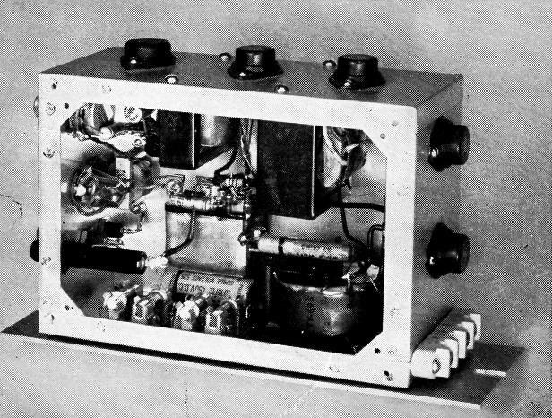
The transistor power supply and modulator. The power-supply oscillator transformer is located at the bottom right in this view. The two transformers suspended from the top surface are the driver and modulation transformers, T2 and T3. Four silicon rectifiers and their mounting clips are at the bottom left, directly below the horn relay, K,. Outputs from the power supply, control circuit and modulator connect to the terminal strip.
The Modulator
As shown in the circuit diagram, Fig. 1, the modulator section uses a two-transistor speech amplifier to provide the gain necessary for driving the Class B push-pull audio power amplifier from a carbon microphone. Push-to-talk operation is included; when the switch on the mike is closed the control relay, K1, closes and turns on the power supply and modulator. K1 is an inexpensive automobile horn relay which can be purchased at most filling stations or auto parts distributors. Current for the microphone is obtained from the 12 volt source through the 220 ohm resistor R1. The microphone transformer, T1, has the gain control, R2, connected across its secondary winding. The audio voltage is applied to the base of transistor Ql through a 5-µf. coupling capacitor. The common-collector circuit is used in order to provide a good impedance match to the base input resistance of the driver transistor, Q2. The output of the driver is transformer coupled to the bases of the Class B modulator transistors.
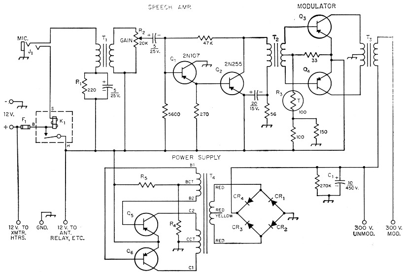
Fig. 1. Schematic diagram of the power supply and modulator. Fixed resistors are ½ watt except as indicated below. Capacitances are in µF; capacitors are electrolytic.
| CR1,CR2,CR3,CR4 | 500 mA silicon rectifiers with mounting clips (Sarkes Tarzian M500). |
| F1 | 10 A fuse. |
| J1 Open circuit, 3 conductor jack. | |
| K1 | 12 volt horn relay (Echlin HR 101; see text). |
| Q3,Q4 | 2N256 or 2N301A. |
| Q5,Q6 | 2N278 or 2N627. |
| R1 | 220 ohms, ½ watt. |
| R2 | 20 kΩ volume control. |
| R3 | 100 ohm thermistor, B value 3300 (Globar 416H*). |
| R4 | 150 ohms, ½ watt, for 2N278 100 ohms ½ watt, for 2N627. |
| R5 | 10 ohms, 2 watts, for 2N278 18 ohms, 2 watts, for 2N627. |
| T1 | Driver transformer; 200 ohm primary, 15,000 ohm secondary (Argonne AR-107, Lafayette Radio, N. Y.). |
| T2 | Transistor driver transformer; 100 mA 100 ohm primary, 100 ohm c.t. secondary (Triad TY-61X). |
| T3 | Modulation transformer, transistor type, 10 watt rating; secondary tapped for 3000, 4000, and 6000 ohms (Triad TY-65Z). |
| T4 | Transistor power transformer, 12 14 volts input, 300 volts, 100 mA d.c. output after filter (Triad TY-695). |
At high transistor temperatures, the transistor leakage current (I.) increases and unless stabilized will "run away" or "avalanche," eventually destroying the transistors. This usually occurs at high ambient temperatures when the transistor power dissipation, caused by self heating, lowers the resistance of the collector. This in turn causes a still greater increase in current, and the process continues until eventually the transistors are destroyed. Since high ambient temperatures are common in mobile operation, a thermistor, R3, is used to confine the operation of the transistors to a safe region. The thermistor (a temperature-sensitive resistor) is placed in the base circuit of the transistors. When the temperature rises, the resistance of the thermistor increases, lowering the base-to-emitter voltage and thus stabilizing Ico.
The power supply
The power supply uses a Triad TY-69S transformer, T4, with two transistors, Q5 and Q5, in a power oscillator circuit. The transistors operate as electronic switches to interrupt the d.c. through the primary of T4 much like the mechanical vibrator does in a vibrator supply.
When voltage is applied to the power supply circuit, current will flow through the transistors; however, since no two transistors are precisely alike electrically, initially one will conduct a little more current than the other. This difference current or "starting" current will cause a small voltage to be induced in the transformer winding connected to the bases of the transistors. The polarity is such that the conducting transistor is biased to conduct even more heavily while the base of the other transistor is biased to cutoff. This process continues until the increasing current causes magnetic saturation of the transformer core, at which time the induced voltage drops to zero and there is no longer enough base bias to maintain the collector current. When this happens the current decreases, causing an induced voltage of opposite polarity. The process then reverses so that the previously nonconducting transistor starts to conduct and the previously conducting transistor becomes cut off. The result is an alternating current of square-wave form through the transformer primary. This in turn induces a stepped-up voltage in the h.v. secondary of the transformer. The frequency is approximately 2000 c.p.s. in this unit.
A bridge rectifier using silicon diodes converts the high-voltage square wave to d.c. Since the rectifier is full wave, the principal ripple component is about 4 kc. This is easily filtered by a single 10 µF capacitor.
Construction
The modulator, power supply and control circuits are all contained in a 3 × 7 × 5 inch chassis. All transistors except Q1 are mounted on the outside surfaces of the chassis walls. The photographs show the two power-supply transistors mounted on one edge and the driver and modulators on another.
It is important that provision be made to insure adequate cooling of the high-power transis tors. Mounting them directly on the chassis would provide an excellent heat sink, but this method is impracticable because the collector terminal is also the mounting flange, and mounting directly on the chassis would short-circuit all the collectors.
A practical method of mounting is to use a common sink but to insulate the collectors from it electrically. At first, one might think this would insulate them for heat transfer as well, but there is only about 0.5 degree per watt difference in temperature between the transistor and sink when a 2-mil (0.002-inch thickness) mica washer is used as an insulator. Sheet mica (sometimes called "isinglass") available at most hardware stores can be used for this purpose if split down into sheets a few mils thick. However, we used polyethylene sheet from a plastic radio parts bag. Be sure to clean and deburr all holes associated with the transistor mounting because any punctures in the insulator will probably result in an electrical breakdown between the transistor and chassis. Insulating washers must be used in places where the transistor mounting bolts pass through the chassis.
Base and emitter terminals on the large audio transistors are small pins on the bottom of the case. Soldered connections to these terminals should be avoided because of the danger of overheating the transistor. A convenient way to connect leads is to use sleeve-lug pin contacts from a miniature tube socket. Flexible leads can be soldered to the lugs, which may then be slid over the transistor pin terminals. The power-supply transistors are supplied with soldering-type base and emitter leads. A soldering lug is placed over the mounting stud for the collector connection.
The two Class B audio transformers, T2 and T3, are mounted on the inside surface of the box along with the low-level audio transistors.
Power transformer T4 is located opposite the audio transformers on the inside of the chassis. Next to it are the four silicon rectifiers, mounted in special clip holders (the holders are furnished with the rectifiers). Directly above them on the chassis is the horn relay. Its location was chosen to make the hot 12 volt lead to the power transformer as short as possible.
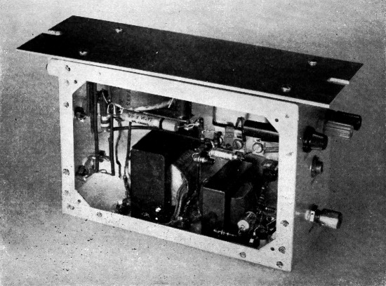
Another view of the two audio transformers. The fuse, mike jack, gain control and battery terminals are at the right projecting through the chassis. A cover plate, not shown in the photographs, should be made to fit over the open side of the box.
Most of the remaining components are visible in the photographs. The gain control, R2, is at the top left in the first view, with the microphone jack, J1, directly below it. The microphone transformer, T1, is behind J1, and is mounted on the inside chassis surface. Terminal strips are used for convenience in mounting the various resistors, capacitors, and transistor Q1.
A plate is bolted to the edge of the chassis so that the unit can be mounted to the automobile. Rubber grommets are placed between the chassis and the plate to act as shock and vibration absorbers.
For quick assembly and disassembly an octal socket and cable plug could be used to connect the unit with the transmitter, instead of the terminal strip shown in the photograph.
Preliminary Checks
It is wise to check the wiring and connections and to test the individual sections of the unit before installation. While checking the modulator, it is a good idea to turn off the power supply to prevent accidental shock. Remove the lead from the emitters of Q5 and Q6 to disable the power supply.
If you wish to observe the wave form of the modulator it will be necessary to connect a scope to the output terminals of T3. Before any measurements are made, be sure to connect a dummy load to the modulator. This can be a 10-watt resistor of the same resistance as the Class C load. The scope is then connected across the resistor. In order to study the output of the modulator it is necessary to apply a sine wave to the input terminals. This can be from an audio oscillator that has some sort of output control. Connect the audio oscillator output across the gain control R2, which should be set at about three quarters of the way on. Increase the output of the audio oscillator and observe the wave shape on the scope. Tips on testing audio equipment are given in the chapter on speech equipment in The Radio Amateur's Handbook.
Measure the a.c. voltage developed across the 10-watt load resistor with a, vacuum-tube voltmeter in order to check the modulator power output. From the formula P = R the power in watts can be calculated. On-the-air tests can give you an idea as to the quality of the audio.
If the modulator fails to operate, use the same trouble-shooting techniques that are used for vacuum-tube circuits. That is, go back one stage at a time, using the scope, until the troublesome section is located. From there on it's usually a matter of finding a faulty component or a wrong connection.
After the modulator is working, connect 12 volts to the emitters of Q5 and Q6. The power supply should oscillate (danger, high voltage!). An indication that the power supply is functioning properly will be a 2 kc audio whine from the power transformer when the circuit oscillates. A voltage measurement across the filter capacitor should show the output d.c. voltage to be in the neighborhood of 300 volts with no load.
Other notes
Once the unit has been completed and checked there is really not much work to installing it. Since the modulator and control circuits are built in, only a few connections are needed and the unit is ready to go. Connect 12 volts d.c. to the power terminals, plug in the mike, connect the leads to the transmitter and you're all set. Important: correct polarity must be observed when connecting the power source; otherwise the transistors will be damaged.
Concerning placement of the unit in the car: Try to find a location away from high-temperature spots and in a well-ventilated area. The trunk is not recommended since there is little ventilation; this area can become quite hot in the summertime and damage to the transistors could result. The engine compartment makes a convenient place to mount the unit but this space is not adequately ventilated except possibly while the car is in motion. The most favorable spot is on the fire wall in the passenger compartment, or under the front seat. These areas are usually well ventilated, or at least cooler than any other enclosed section of the car.
E. Laird Campbell, W1CUT.