A desktop 650 watt amplifier
External-anode tubes offer a good opportunity to build a compact amplifier, and when they are combined with such things as germanium diodes in the high-voltage power supply you can build a potent package on one chassis. The plate circuit in this amplifier will be quite a shocker to the current generation that has been led to believe that the only possible output circuit is a pi network.
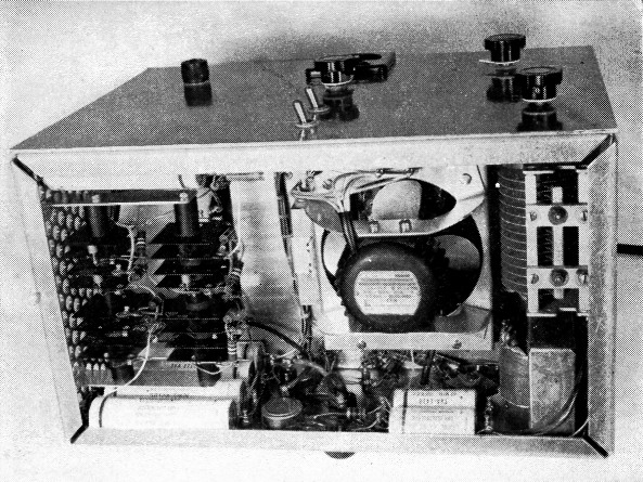
Smaller on the outside - bigger on the inside.
For about fifteen years this author has been nursing a desire for a kilowatt rig in a desk-sized (or pocket-sized) cabinet. The linear to be described is the most recent effort in that direction. It is not pocket sized, but you can tuck it under your arm and haul it off to a remote QTH.
Despite its small size and innocent appearance, this amplifier packs as much wallop as many larger ones, and it can be dangerous to life and limb. Its construction should not be attempted by the inexperienced.
The rig, when driven by an exciter such as the HT-30, of 30 watts nominal output, runs at about 650 watts plate input and gives about 400 watts c.w. or peak envelope output. It covers 80 through 10 meters by means of band switching. Like the HT 30, it has a fixed 50 ohm output impedance.
The amplifier is built on an 8 × 14-inch chassis with a 10 × 14-inch panel. The chassis is 434 inches deep, to provide space for the filter capacitors and cooling fan underneath. As can be seen by studying the photographs, the plate power supply occupies the left end of the chassis, and the r.f. circuits take most of the remaining space. The heater and bias supply is stowed under the right rear corner of the chassis behind the plate tuning capacitor. The screen regulator and standby relay are at the rear of the chassis in the center.
The controls are few and simple. The band switch has four positions, for the 80, 40, 20, 15 and 10 meter bands. Other controls are the plate tuning capacitor, plate-current screen-current meter switch, power and plate voltage switches.
R.F. circuit
The r.f. portion uses two 4X250B tubes in grounded-cathode connection, operating Class AB2. 4X150A tubes work just as well, although the available plate voltage exceeds their ratings.
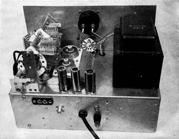
This single package hardly seems big enough to contain the full works of a 650-watt amplifier, power supply and all. The secret lies in the use of 4X250B tubes and a germanium-diodes power supply. Small tube shields house voltage-regulator tubes and a relay.
Referring to the circuit in Fig. 1, no grid tuning is provided, since the output voltage from the HT-30 is enough to drive the grids directly. A 110 ohm swamping resistor in the grid box is made up of eight 220 ohm 2 watt resistors in series-parallel. The r.f. goes to the grids through a 470 pF coupling capacitor; the small coil Ll is a series peaking coil that was included to make the amplifier a little easier to drive in the 10 meter band.
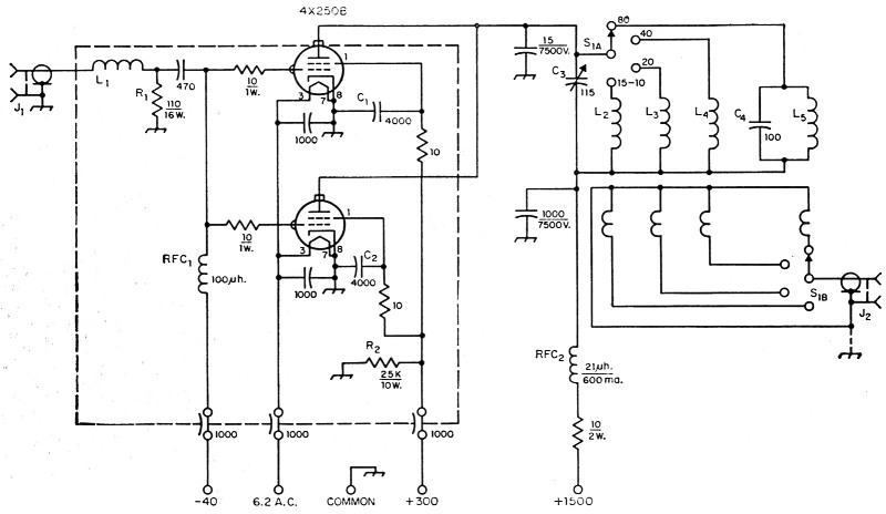
Fig. 1. Circuit diagram of the r.f. portion of the amplifier. Unless otherwise indicated, capacitances are in pF, resistances are in ohms, resistors are ½ watt. The 1000 pF plate bypass is a CRL Type 858-S; the 1000 pF feed-through capacitors are 500 volt ceramic.
| C1,C2 | Four 1000 pF 500 volt disk ceramic capacitors in parallel. |
| C3 | 20-115 pF variable, 2000 volt spacing. See text. |
| C4 | Two 25 pF NP0 ceramic and one 50 pF N750 ceramic in parallel, 7500 volt rating. |
| J1 | UG-291/U BNC panel jack (Amphenol 31-001). |
| J2 | SO-239 UHF panel jack (Amphenol 83-1R). |
| L1 | 6 turns No. 20, 1 inch diam., ½ inch long. |
| L2 | 4½ turns 1/8 inch copper tubing, 1¼ inches long, 1½ inch diam. Link is 3 turns No. 16 wire, ¾ inch long, ¾ inch diam. |
| L3 | 6 turns 1/8 inch copper tubing, 1½ inch long, 1_5/8 inch diam. Link is 2 turns No. 12, ½ inch long, 1_1/8 inch diam. |
| L4 | 8½ turns No. 12, 1_1/8 inches long, 2_1/8 inch diam. Link is 3 turns No. 12, 3/8 inch long, 1½ inch diam. |
| L5 | Two coils, see text. Outer is 10 turns No. 12, 1_3/8 inches long, 2½ inch diam. Inner coil is 6½ turns No. 12, ¾ inch long, 1¾ inch diam., inside plate end of outer coil. Link is 4 turns No. 12, ½ inch long, 1½ inch diam. |
The output circuit might almost be called unconventional these days. A parallel-tuned circuit and fixed link are used, and both are switched on each band. This has several advantages over a pi network, especially over the fixed-outputimpedance type now becoming popular. No parallel-feed choke is needed. No large pi-output capacitor is needed. Tuning is straightforward and much simplified. The coupling, once adjusted, holds over a wide frequency range.
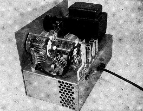
In this side view two of the feed-through insulators that support the plate capacitor and the coils are visible in the foreground.
The link circuit is grounded through a removable jumper at the output connector, so that a balanced load could be fed if desired.
The small 15 pF capacitor (CRL Type 850), from the plates to ground, provides a short path for harmonic currents and keeps them out of the output coil. On the 3.5- to 4-Mc. range a fixed 100 pF capacitor is connected right across the coil, so that a respectable L-to-C ratio can be maintained at 4 Mc. When switched out of the circuit, the coil and fixed capacitor resonate around 5 Mc., which does not bother any of the other ranges.
The 10 ohm resistor in the B+ lead serves as a fuse in case of a shorted tube or other fault that might endanger the power supply.
Power supply
The plate supply uses two voltage doublers in series; see Fig. 2. Two 325 volt windings on T2 feed strings of germanium rectifiers in full-wave voltage-doubler connections. Each doubler capacitor is 160 µF, made up of two paralleled 80 µF 450 volt cartridge type units with cardboard sleeves. The chassis is lined with insulating material under the C5 and C6 capacitors, since their outer cans run as high as +1300 volts. The ripple is around 3 per cent r.m.s., and the regulation from no load to full load is about 15 per cent. The rectifier stacks were assembled from cells salvaged from G.E. germanium bridge rectifiers. (While these rectifiers have many virtues, they do not like having the output shorted.) Each cell is rated at 500 mA d.c. and 300 volt peak inverse; the nearest equivalent is the G.E. 1N153. Sixteen cells are used. Each group of four cells in one side of a voltage doubler has two 560 K resistors connected across pairs of cells to equalize the reverse voltage drop. Other 560 K resistors are connected as bleeders only as a safety measure, since no bleeders are needed for proper circuit operation. But even with the bleeders, the capacitors can retain a charge for several minutes, so be careful!
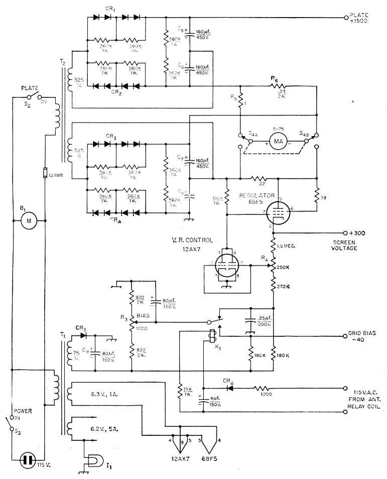
Fig. 2. Circuit of the power supply. Unless otherwise indicated, resistances are in ohms, resistors are ½ watt.
| B1 | 3250 r.p.m. motor with 4 inch fan blade. See text. |
| C5,C6,C7,C8 | Two 80 µF electrolytics in parallel (Sprague TVA-1716). Insulate as described in text. |
| CR1-CR4 | Four 500 mA, 300 volt peak inverse (1N153 or equiv.). |
| CR5 | 100 mA 380 volt peak inverse. |
| CR6 | 65 mA 380 volt peak inverse (Federal 1002A). |
| I1 | 150 mA 6-8 volts (GE No. 47). |
| K1 | 5000 ohm coil, 4 mA pull-in (Terado Series 600 or equiv.). |
| R3 | 2 watt linear potentiometer (Ohmite CU-1021). |
| R4 | 2 watt linear potentiometer (Ohmite CU-2541). |
| S2,S3 | 15 A 125 volt toggle (Cutler-Hammer 7501-K13). |
| S4 | Two-pole 2 throw 60 degree throw ceramic rotary switch, non-shorting. See text. |
| T1 | 6.2 volt at 5.5 A, 6.3 volt at 1 A, 75 volt at 100 mA (Forest Electric Co. T-423). |
| T2 | Two secondaries, each 325 volt at 1 amp. (Forest T-412). |
Grid bias is furnished by a 75 volt winding on T1, a half-wave rectifier and an 80-µf. capacitor. About -90 volts is developed across C9 and applied to the tubes during stand-by periods. The operating bias is adjustable from -30 to -60 volts by R3.
Screen voltage is taken from the +375-volt point of the plate supply (junction C7 and C8). It is dropped through the 6BF5 voltage regulator to deliver a low-impedance output adjustable from about 250 to 325 volts at up to 75 ma. Since this type of regulator will not handle reverse current, bleeder R2 is provided to offset no-signal negative screen current drawn by the 4X250Bs and make the screen meter read on scale.
When in operating condition, the "reference" voltage for the screen regulator is the -90 volt bias supply. In stand-by condition the reference is switched down to the tap on R3, thus reducing the screen voltage from its nominal +300 or so to a lower value. This action, together with the increased grid bias, insures that the 4X250Bs draw no current in standby condition. In operation the grid, screen, and plate voltages all tend to vary in proportion to line-voltage changes.
The screen current is measured by switching the 0-75 milliammeter across 22 ohms in the lead to the screen-voltage regulator. The resistor has negligible shunting effect. For measuring plate current the meter is switched across a low resistance Rs, connected between the two sections of the plate supply. 14 was adjusted for full-scale meter reading at 750 ma. There is a maximum of 425 volts between switch contacts and 850 volts from contacts to ground.
The stand-by relay K1 is one that plugs into a 7 pin miniature socket. It operates from 115 volt a.c. and a half-wave power supply. The input is brought out to two terminals on the rear of the chassis, where connection is made across the antenna relay coil, which in turn is connected through the HT-30 VOX relay to the 115 volt line.
Construction
As usual with a compact layout, some tight spots were encountered; an extra half inch here and there would have helped. For example, the tubes could have been moved to the left to leave more room for the low-frequency coils.
The plate tank capacitor is one from a BC-375 tuning unit, mounted under the chassis on four ceramic feed-through bushings. Four holes were drilled and tapped in the ¼ inch square frame rods on the right-hand side of the capacitor, and 6-32 threaded rod was screwed into the holes and passed through the insulators. The four screws project above the insulators at the top of the chassis, where the B+ ends of the plate coils connect to them via copper strips. An insulated shaft extension goes through the panel to the tuning knob.
The wire from each coil was wrapped around a pipe of suitable diameter. Four Plexiglass strips were drilled with clearance holes at the desired spacing, then the coil wire was fed through the holes. The 80-meter coil was made with two concentric sections in series to get enough inductance into the available space. The 80- and 40-meter links were also threaded through strips, while the 20- and 10-meter links are self-supporting. All links are a push fit inside the insulating strips of their respective coils, and are held with a drop or two of cement after adjustment.
The two band-switch wafers are each single-pole, 4-position, 60-degree throw (Communications Products Co., Type 86). For 8 dollars, the manufacturer sent me the two wafers plus extra common contacts. (The standard common contact wipes on one side only of the rotor. The extra contact was fastened under the standard one with 2-56 hardware to make it double-wiping, probably an unnecessary precaution). A 60-degree index-and-shaft assembly from an Oak Type H switch was used, since it fitted nicely in the available space. The rest of the switch was made up from 6-32 threaded brass rod, %inch o.d. tubing, 1/16-inch aluminum sheet, and miscellaneous ceramic spacers and fiber washers from junked rotary switches.
The front wafer switches the plate coils. The links are connected to the rear wafer through RG-58/U cable, except the 80-meter link which goes direct. The cold sides of all links are soldered to a strip of copper running around the wafer, supported by 2-56 screws through the unused holes between contacts. The u.h.f: type output connector is mounted on a strip of bakelite fastened totherear switch bracket; its shell is grounded through a couple of solder lugs.
The transformers were designed for us by W9PZZ, who just happens to work for the Forest Electric Co. The company would consider making up a few of the transformers if any interest is shown. T2 weighs about twenty pounds; the chassis should be at least 0.08 inch aluminum to be strong enough to carry it.
A bottom cover and a perforated-metal shield over the top, sides and rear are going to be added, for safety as well as TVI-proofing. An opening will be cut above the r.f. tubes and covered with hardware cloth.
Cooling
Each 4X250B tube requires at least 3.6 cubic feet of air per minute through the anode cooler. The base also requires some air. The tube is ordinarily mounted in an Eimac "air-system" socket so that the air flows first over the base, then through the anode cooler. This leads to a fairly large pressure drop, which is ordinarily considered to require a centrifugal blower. These are uncommon items and are very difficult to fit into a compact layout.
Accordingly, it was decided to try a fan. To reduce the pressure drop, only the insulating rings and contacts from Eimac sockets were used, mounted by the cathode tabs in oversized holes in the chassis. Many small holes were drilled in the chassis to provide additional air passage. A small aluminum housing above the chassis directs all the air through the anode coolers. It comes to within ¼ inch of the anode coolers. The opening is closed by a piece of Fiberglas-base plastic fitting on top. It comes to within 1/16 inch of the tubes, so that a small amount of the air flows around the outside of the coolers.
All of the left end and part of the right end of the chassis are perforated by 3/8 inch holes. The air drawn in by the fan passes over the plate rectifier fins and past the heater transformer. The whole air path is direct and free from large obstructions and sharp bends.
The fan is a 4-inch blade driven by a Rotron Mfg. Co. Type 92-AS motor at 3250 r.p.m. It is mounted in a hole 4% inches in diameter in the grid housing, with about 3 of the blade thickness projecting into the housing. The motor is a capacitor-run type. The 1 µF 600 volt phasing capacitor mounts on the side of the grid housing.
A husky 4-inch fan and the stack of germanium rectifiers are prominent objects in the bottom view. The plate tuning capacitor (right) is insulated from the chassis, as described in the text.
The motor, housing and capacitor can be removed as a unit, leaving only the front and rear walls of the housing in place.
While a split-phase or other small a.c. motor could be used, most of them run a bit slower than this. The extra speed is handy, especially when cooling 4X150A tubes, which want a bit more air. Series motors are not recommended because of the r.f. interference generated at the brushes.
Under the conditions described, the pressure vs. flow curves of the fan and of the tubes indicate that somewhere around 10 c.f.m. of air is delivered. This is ample for a pair of 4X250Bs but barely sufficient for 4X150As. In practice, no difficulty has been experienced in cooling a pair of 4X150A tubes. Since the only major source of heat is the tubes, and since this heat is quickly removed by the air, the whole amplifier runs cool.
Operation
No published ratings are available for 1500 volt Class AB2 operation of these tubes. We have been setting the screens at +300 volts, and the grid bias at a point (about -40 volts) where the tubes draw 150 mA with no drive. When operating and properly loaded, full output from the HT-30 swings the plate current to 400 mA or so.
The various links are of approximately the right inductance to couple to a 50 ohm load. They must be quite tightly coupled to their plate coils. When properly positioned with a 50 ohm load connected, the plate current dips 10 or 15 mA as the plate capacitor is tuned through resonance with r.f. drive applied. Once adjusted, these links are left alone. The antenna is tuned with the aid of an s.w.r. bridge to present a 50-ohm load to the amplifier. The amplifier should not be operated without a suitable load.
Operation is now very simple. The heaters are warmed up for at least 30 seconds. With the plate power switch off, the band switch is set to the proper range. The exciter is tuned up to give c.w. output. (Not more than 40 volts r.m.s.) The plate power is turned on and the plate capacitor tuned to the plate current dip, or to maximum indicated output if a Micromatch is being used. The exciter is then set to give the type of output desired.
No startling DX claims are made for this rig, since operating is not our strong point. However, the amplifier gets 10 or 15 dB better reports than the barefoot exciter, and solid contacts are now the rule rather than the exception.
James M. Lomasney, W9LZV.