Simple low-pass filter design
Easy calculation of values in a high-performance circuit.
Circuit constants for low-pass filters having a wide range of attenuation characteristics can quickly be obtained from the data given in this article. W2WZR uses an audio filter of this design to improve signal-to-noise ratio and relieve listening fatigue in weak-signal v.h.f. reception.
NY amateur can construct excellent low-pass filters of the Chebychev type if the following things are known:
- Terminating resistance.
- Cut-off frequency.
- Minimum desired attenuation in the stop band.
Fig. 1 gives the circuit of such a filter having a reasonably sharp rate of cut-off. The lower drawing of this figure shows where the cut-off frequency is in relation to the end of the pass band and the beginning of the stop band. The numerical relationships between these frequencies, for various amounts of stop-band attenuation, are given in table 1, together with values of L and C normalized to an impedance of 1 ohm and one cycle per second.
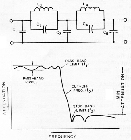
Fig. 1. The filter circuit and representative attenuation characteristic. Table 1 gives normalized values for circuit constants, pass-band and stop-band limits, for a maximum of 1.0 dB ripple in the pass band.
Chebychev filters have amplitude ripples in both the pass band and stop band. By proper design the amplitude of the ripple in the pass band can be held to any desired value. However, 1.0 dB ripple is adequate tolerance for amateur work and Table 1 is calculated on this basis.(1)
How to use the table
| Minimum stop-band attenuation | Pass-band limit (f1) | Stop-band limit (f2) | Capacitance in Farads | Inductance in Henrys | |||||
|---|---|---|---|---|---|---|---|---|---|
| C1 | C2 | C3 | C4 | C5 | L2 | L4 | |||
| 35 dB | .935 | 1.070 | .3035 | .0807 | .3366 | .2531 | .2173 | .1409 | .0831 |
| 40 dB | .907 | 1.103 | .3266 | .0653 | .3759 | .1943 | .2504 | .1531 | .1014 |
| 45 dB | .896 | 1.116 | .3416 | .0520 | .4079 | .1506 | .2758 | .1682 | .1214 |
| 50 dB | .843 | 1.186 | .3650 | .0422 | .4515 | .1183 | .3088 | .1818 | .1417 |
| 55 dB | .809 | 1.236 | .3888 | .0350 | .4956 | .0958 | .3408 | .1940 | .1596 |
| 60 dB | .773 | 1.294 | .4132 | .0291 | .5394 | .0783 | .3721 | .2066 | .1775 |
| 65 db | .737 | 1.357 | .4398 | .0244 | .5836 | .0649 | .4046 | .2195 | .1947 |
| 70 dB | .701 | 1.427 | .4668 | .0202 | .6204 | .0543 | .4378 | .2335 | .2122 |
The table lists values for C1, C2, L2, C3, C4, L4 and C5 as a function of the minimum desired stop-band attenuation. Capacitance values given are in farads and inductance values are in henrys. Since the values are normalized they must be converted to the appropriate frequency and impedance levels. For the frequency transformation all the L and C values given on the selected dB attenuation line must be divided by fo, the cut-off frequency chosen. For the impedance transformation divide the capacitance values by the chosen value of terminating impedance (this should be purely resistive) and multiply the inductance values by the chosen value of terminating impedance. The two operations (frequency and impedance transformation) can be combined as follows:
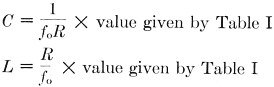
To find the pass-band and stop-band limits, multiply the cut-off frequency by the normalized values for these limits, for the stop-band attenuation selected, as given by Table I.
An example
Say we want to work at an impedance level of 1000 ohms and we want the cut-off frequency to be 2500 cycles per second. We also want a minimum of 60 dB attenuation in the stop band.
From Table I we can immediately find the start of cutoff by looking in the 60-dB set of values, finding 0.773 as the factor for the pass-band limit. Then
![]()
The stop-band limit, from the Table, will be 2500 times 1.294, or
![]()
The attenuation characteristics of the filter can now be estimated as shown in Fig. 2.
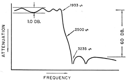
Fig. 2. General shape of attenuation characteristic of the filter calculated in the example.
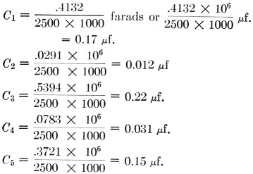
The L and C values are calculated as follows:
As a short cut, the value of the expression
![]()
may be calculated first, and then multiplying the C values given in the Table by this factor will give the values of the various capacitors directly. A similar short cut,
![]()
may be used(2) for finding the L values:
![]()
These values are all we need, and the complete filter is shown in Fig. 3.
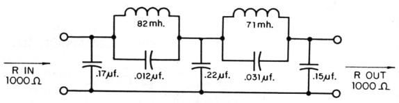
Fig. 3. Circuit constants of the filter calculated in the example.
Components
For best results the actual filter should use component values as close as possible to the calculated values. If possible, the capacitances and inductances should he measured on a bridge.
The theoretical design is based on loss-free components, but capacitors and inductors with a Q of 50 or better will give excellent results. Mica capacitors are preferred; however, good-quality paper units may be used for the larger values.
The most critical component is L4, which is in a parallel-tuned circuit producing an attenuation notch nearest the pass band. This coil therefore should have as high a Q as possible. Powdered-iron toroidal cores are best. Suitable cores can be obtained from the Arnold Engineering Company, Marengo, Ill., and the following types are recommended:
B-064157-3
A-930157-2
E-115157-4
D-671157-3
W-098157-3
Coils wound on any of the above cores have a nominal inductance of 157 millihenry for 1000 turns of wire. Since inductance varies as the square of the number of turns, any desired value can be quickly approximated - e.g., 500 turns would give about one-fourth of 157 mH or 39.2 mH.
Hand winding is not too difficult if a bobbin with slots in the ends is made up of brass or aluminum rod, as shown in Fig. 4, and passed through the center of the toroid after first having been wound full of wire of a size appropriate for the inductance required and the winding space available on the toroid core.
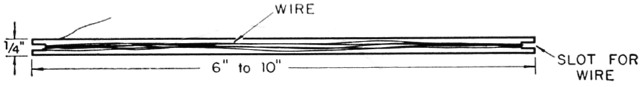
Fig. 4. Bobbin for winding toroidal inductances.
Choice of impedance level
In order to achieve the theoretical performance of the filter the proper terminations must be used; that is, the signal source feeding into the filter should have the chosen value of internal resistance, and the output side of the filter similarly should work into the same value of resistance.
Any convenient value of impedance can be selected, but occasionally a choice is made that will require impracticable values of L and C - e.g., very high values of R will lead to extremely large values of inductance and very low values of R will lead to very large values of capacitance. If the design turns out to be poor on this account, it will be necessary to reconsider your choice of impedance. In general, an impedance value of the order of 600 ohms is a good choice for speech work as the component values are reasonable. However, there is considerable latitude.
If the output of the filter is applied to the grid circuit of an amplifier tube - usually this will be the case - the termination on the output side can be a simple resistor having a value equal to R. On the input side the filter can be coupled to the preceding tube by means of a transformer having the proper impedance ratio for the tube and filter, unless R happens to be, or is deliberately chosen to be, equal to the internal output impedance of the driving amplifier. A cathode follower makes a good driver since its internal output impedance will be in the neighborhood of a few hundred ohms, a good value from the standpoint of values of components used in the filter.
Fig. 5 shows the circuit of an amplifier built by the author using the values computed above. In this case the input side of the filter is coupled to a 12AU7 section through a step-down transformer to match the plate resistance of the tube to the 1000 ohm impedance of the filter. The second half of the 12AU7 drives a 6AQ5 output amplifier with the writer's "secret weapon" for combating line noise - a series-resonant circuit tuned to 60 c.p.s. - in its grid circuit. In v.h.f. reception the low-pass filter, by eliminating unnecessary high-frequency response, has practically eliminated the strain of listening to a dead band; and with the "secret weapon" a large amount of line noise can be tolerated. The filter is particularly effective for scatter communication, and it is surprising how little distortion of voice signals is apparent even though cut-off starts at about 1900 c.p.s.
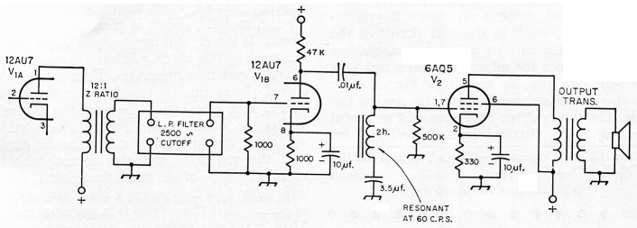
Fig. 5. The author's amplifier, incorporating a filter as designed in the text and the "secret weapon"-a series-resonant trap in the grid circuit of the output tube-for reducing line noise.
Notes
- Adapted from tables in a paper by Bedrosian, Luke and Putschi, On the Tabulation of Insertion Loss Low-Pass Chain Matrix Coefficients and Network Element Values," Proceedings of the National Electronics Conference, Vol. XI, 1955.
- It is merely a coincidence that the short-cut factors happen to be the same for both C and L in this example.
James V. O'Hern, W2WZR.