Helical element ground plane
20-15-10 antenna with 10 meter dimensions.
Helixes of the long, thin type have been used as antennas off and on for a long period, particularly in mobile installations. This, however, is the first time we have heard of their being used for ground-plane radials - and for multiband operation using traps.
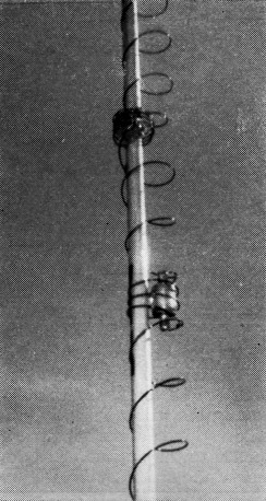
The 10 and 15 meter traps installed between helixes. The traps are preset to frequency before installation, and adjusted for best input-resistance characteristics of the antenna in the final tuning process. Adjustment is by changing turn spacing.
A new antenna was needed desperately for 20 meters. Locals on this c.w. band were putting me to shame when they showed me their latest logs. A vertical or ground-plane antenna with its low-angle radiation should solve the DX problem, but complications arose. Problems of obtaining a good ground system and situating the antenna away from a maze of elm trees eliminated a conventional vertical from consideration, and a full-size ground plane was out of the question because this QTH has a tiled slanted roof. However, a ground plane with 10-meter dimensions would solve any difficulties.
Last summer W5AIG introduced a new antenna concept to me, the helical monopole. He mentioned that research indicated that a normal-mode(1) helix compared closely in efficiency with a straight vertical element. I decided to investigate a ground plane with helical radials.
What started as a wild idea has now evolved as a tri-band miniature ground plane. Excellent results have been obtained on 10 and 20 meters. Stateside response and reports on 20 meter c.w. compare very closely to a regular ground plane, and DX has been good. The ground plane has opened a "new" 10 meter band with its ground wave. DX contacts on 10 meters show that the ground plane is never more than two "S" units below a three-element beam. Unfortunately, results on 15 meters have only been fair; occasionally this band does favor the ground plane, but usually my dipole pulls ahead with stronger signal reports. The ground plane also is grand for band scanning during contests and DX openings.
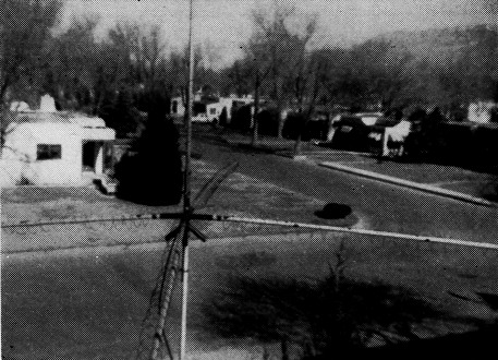
While the wire helixes do not stand out too well in this antenna photograph, enough should be visible to give the general idea. Simple helixes are used in the radials; only the radiating element is trapped for multiband operation.
Band-changing operations are kept to a minimum since only one feed line having a fairly constant input impedance at the transmitter is used. The antenna is fun to construct, and the total cost is about thirty dollars.
Principles
Each element is wound in the form of a spiral. Turns of the helix can be thought of as forming an imaginary cylindrical surface. The length from end to end of this imaginary cylinder at resonance will be shorter than the length of a straight wire in space resonant at the same frequency. The inductive and capacitive reactances cancel at resonance, leaving the cylinder resistive. The total length of wire in a quarter-wave helix is greater than a quarter wavelength; for example, the wire length in a typical 14 Mc quarter-wave helix is not sixteen feet but twenty-six feet. When the helix is compressed the resonant frequency rises (provided the turn spacing remains large compared to the wire diameter), and if no turns are added to the compressed helix it will be reactive at the original frequency but resistive only at some higher frequency. Tuning a helix is simple, since the resonant frequency may be raised by compressing it or lowered by stretching.
By changing the diameter and turns per inch, helixes may be made resistive at a given frequency although their length may vary greatly. One unfortunate thing happens, though, as a helix is shortened. The radiation resistance, which is a principal factor in determining the efficiency of a short antenna, is largely dependent on the length of the element. A conventional ground plane at resonance will have a radiation resistance around 32 ohms. If the length of a radiating element is cut down to, say, an eighth wave, it will have a lower radiation resistance whether it shows reactance or not. I found a helical ground plane of these dimensions to have an input resistance of 21 ohms on 14 Mc.
For multiband operation the radiating element is broken up into resonant sections separated by parallel-resonant traps as shown in Fig. 1. At the frequency to which it is resonated each trap shows an extremely high impedance and separates the remaining sections of the helix from the resonant section. A high C to L ratio is used in the traps to reduce resistive losses and to increase the band width.
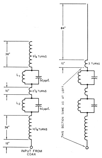
Fig. 1. Dimensions of radiating element. The arrangement at the left is the one used by the author; that at the right is a suggested modification to raise the input resistance on 14 Mc. Helixes are made of No. 12 wire.
L1 4 turns No. 12, 2¼ inch diam., 1 inch turn spacing.
L2 3 turns No. 12, 3½ inch diam., ¾ inch turn spacing.
Impedance measurements for the three bands were first taken with individually resonated helixes and then with the traps installed. The results are shown in the table below:
| Frequency | Helix without traps | Helix with traps |
|---|---|---|
| 28.6 Mc | 150 ohm | 145 ohm |
| 21.3 Mc | 75 ohm | 100 ohm |
| 14.1 Mc | 21 ohm | 17 ohm |
The radiation resistance should be and can be increased. Although I used a nine-foot dowel for the driven element, I suggest that you buy a thirteen-foot section; at longer lengths, the dowels begin to bend. Instead of using a helix for the 20 meter section, run a straight wire from the top of the pole and extend the wire into a three-turn coil before soldering it to the 15 meter trap.
Two quarter-wave transformers in series are used to obtain good impedance matches at the transmitter, as shown in Fig. 2. A quarter-wave transformer of RG-8/U is used on 20 meters to step up the 17 ohm impedance at the antenna to approximately 160 ohms at its input. This gives a good match (less than 2:1 s.w.r.) with the main feed line, the 93 ohm RG-62/U. If the input resistance of the antenna is raised to 29 ohms on 20 meters, a perfect match will result. On 10 meters the 14 Mc quarter-wave transformer becomes a half-wave and repeats the 145 ohm impedance seen at the ground plane. The RG62/U coax is an odd quarter-wave section on 10 meters and drops this 145 ohms down to 60 ohms at the transmitter. On 15 meters the impedance bridge connected to the input end of the 14 Mc coaxial section gave the same 100 ohm impedance reading as did the antenna itself. The mismatch between this value and the RG-62/U is slight.
Construction
Before tackling this antenna, bottow grid-dip, impedance, and s.w.r. meters if you don't have them already. This equipment is essential for tuning the ground plane; it is also an excellent investment for any ham shack.
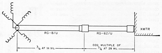
Fig. 2. Transmission-line system used for maintaining relatively constant line input impedance on the three bands. The length of the RG-62 U section may be any odd multiple of a quarter wavelength (at 10 meters).
A search for a mounting unit led me to K2GSO's "Happy Accident" ground plane(2) to which I added several modifications. To give a greater clamping area, a 30 inch length of angle iron was used instead of the prescribed 16 inch length. Two pairs of radial supports were welded, one set at the 30-degree angle and the other set perpendicular to the angle iron. (The latter set is used in the present antenna.) The supports were made of a thicker diameter, 14-inch black iron water pipe. This mounting unit was extremely heavy and awkward to work with; I urge the builder to use only one set of radial supports and to construct the unit out of aluminum.
First, choose five straight lengths of wooden dowels. Since the water pipe used for the radial supports is smaller in diameter, cut down the diameter of the first six inches of each of the four 9-foot dowels to fit. The four dowels should be drilled for the bolts which hold them in the radial supports. Give them two coats of varnish.
The coil of No. 12 wire should be cut into five 28-foot sections which are then close-wound on a 2½ inch form. Wind all the coils in the same direction. Tin one end of each coil and solder lugs to four of them. Place one coil on a dowel situated in a horizontal position and insert a half-inch screwdriver handle between the first two turns. Next, start turning the coil until the screwdriver winds itself to the opposite end. Continue increasing the width of the object placed between the windings until the spacing between turns is about 3% inches. Place the helix on the dowel so that the solder lug coincides with the drilled hole in the dowel. The first five feet of each helix may be glued to its dowel, leaving the remaining four feet of coil for tuning adjustments. I used electrical tape on every fourth turn.
Traps and Transformers
The parallel traps and coax transformers require a grid-dip meter and impedance meter for adjustment.
A variety of capacitors may be used for the traps. I pulled two out of the junk box: one was a 15 kV plate capacitor and the other was a 5 kV filament by-pass capacitor which has worked splendidly. The 10-meter trap consisted of three turns of 3½ inch diameter wire spaced ¾ inch apart while the 15 meter trap used four turns with a 2¾ inch diameter and 3/8 inch spacing. The traps should be kept away from metallic objects when being resonated, which should be (lone before installation. You should get a pronounced dip on a grid-dip meter when it is placed near the trap. Since the traps will pull the oscillator of the grid-dip meter, a receiver should be used as a calibrating unit. Resonate the traps at 28.6 and 21.3 Mc.
Solder a male coax connector on one end of each coax line and connect the RG-8/U section to the impedance meter. Set the impedance meter to minimum impedance and, using your receiver as a calibrating unit, set the grid-dip meter to 14.15 Mc. Start clipping the opposite end of the coax until the lowest impedance dip is obtained. This 20-meter coax section is now a quarter-wave transformer and should be 10.8 feet long, or an odd multiple of this value. Follow the same procedure with the RG-62/U section, using a frequency of 28.6 Mc. The length of this 10-meter transformer is 5.4 feet or an odd multiple of this figure.
Tuning
This ground plane should be tuned in its permanent location, or at least at as near the same height as possible. First, bolt the four radials with their solder lugs in the radial support. Then couple the grid-dip meter to the first or second turn of any radial; a weak dip should be obtained. Clip off turns at the end of this radial until it resonates at 13 Mc. Using the same procedure, resonate the other three radials at 13 Mc. and then retune all four to 13.6 Mc. To do the final resonating, either compress or stretch the four feet of loose coil on each helix. Glue the coils to their dowels.
The driven element is harder to tune. First resonate an eleven- or twelve turn helix at 28.6 Mc. It was found that the tinned end of this helix can be bent ninety degrees and slipped in and out of the female coax connector, making tuning a simple matter. Solder the 10 meter trap to the 10 meter helix and add five turns for the 15-meter section. In a similar manner cut down the 15 meter section until it resonates at 21.3 Mc. Two dips can now be obtained, one at 15 and the other at 10 meters. Next add the 15 meter trap. Instead of using a helix for the 20 meter section, I suggest that you solder a three-turn coil to this trap and extend the rest of the wire straight up the dowel to increase the radiation resistance.
The parallel traps are very critical since changing the spacing of the turns a quarter inch will mean the difference between a good or poor match. Connect the impedance meter to the antenna and change the turn spacing until a resistive reading (i.e., a sharp null) can be obtained. I found my best resistances on 10 and 15 meters to be 145 and 100 ohms.
Final checks should be made with an s.w.r. bridge in the coaxial line.(3) If the s.w.r. is high on 15 meters, very slight changes in the 15 meter trap will reduce the reflected waves to a minimum.
Finish gluing the sections to the pole and paint all exposed parts with glyptal.
Most important, get that ground plane in the air! Happy hunting!
The author would like to acknowledge the valuable suggestions and assistance of Paul Brace, K5HXT, Burt Bittner, W5AIG, Earl Fletcher, W5WRS, and Loren Watkins, W5JX0.
Notes
- I.e., maximum radiation in the plane perpendicular to the axis of the helix (corresponding to the radiation from a straight-conductor dipole or monopole) as contrasted with the helical antenna of Kraus. The characteristics of this type of antenna have been analyzed in a paper by Kandoian and Sichak, "Wide-Frequency-Range Tuned Helical Antennas and Circuits," Convention Record of the I.R.E., Part 2, 1953 National Convention. - Ed.
- Hammond, "The 'happy accident' ground plane," QST, January, 1957.
- The bridge should be set up to match the 93-ohm impedance of the RG-62/1.
Ralph Rosenbaum, W5ECP.